Description of the appliance
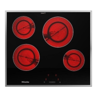
KM 84-2 / KM 87-2
b Control panel
c Cooking area - Ø 14.5 cm
d Cooking area - Ø 18 cm
KM 87-2: Halogen
e Residual heat indicator
f Connection cable with plug,
approx. 1.10 m long.
N.B. Plug according to country.
g Control for the front cooking area
h Cooking area indicator lights
i Control for the rear cooking area
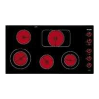
KM 94-2 / KM 97-2
b Control panel
c Cooking area - Ø 18 cm
KM 97-2: Halogen
d
Cooking area - Ø 14.5 cm
e Cooking area - Ø 14.5 cm
KM 97-2: Halogen
f Cooking area - Ø 18 cm
g Connection cable,
approx. 1.30 m long
h Control for the front right cooking
area
i Cooking area indicator lights
j Control for the rear right cooking area
k Residual heat indicators
l Control for the rear left cooking area
m Control for the front left cooking area
Data plate
Because the data plate is no longer
visible once the appliance has been
built in a 2nd data plate is supplied
which should be stuck into the space
provided on page 15 of these instruc-
tions under After Sales Service.
Special accessories
Special accessories are available from
your Miele Dealer or from the Spare
Parts Department.
Stainless steel cover EA 80
A stainless steel cover is available for
the KM 84-2 / KM 87-2 ceramic hobs.
Check availability in each country. For
installation of the cover a minimum dis-
tance of 510 mm (or respective dis-
tance for cooker hood in installation in-
structions) is required between the
worktop and wall units.
Description of the appliance
5
 Loading...