This document provides a comprehensive manual for the MIJO Handbike Attachment, available in models MT01 and MT02, designed to enhance the mobility and freedom of wheelchair users. It covers product description, installation instructions, battery usage, and warranty information.
Function Description
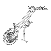
The MIJO Handbike Attachment is a motorized device designed to convert a manual wheelchair into a powered handbike, enabling users to navigate various environments with greater ease. It integrates a disc brake system, a combination switch, handlebars, a meter, a power switch, a pneumatic tire, a quick-release pin, a foot support, a fender, reflectors, and a motor. The device is powered by a lithium-ion battery, which can be locked and secured with a key. The handbike is suitable for both outdoor and indoor use, including hospitals, nursing homes, and homes. It is specifically intended for disabled individuals and the elderly with mobility difficulties. The motor provides power assistance, and the device is equipped with a brushless DC motor and a brushless DC sine wave controller for efficient operation.
Usage Features
The handbike attachment offers several features to ensure ease of use and safety.
Installation and Connection:
- Foot Support Installation: The foot support is easily installed on the frame using a 5mm inner hexagon wrench.
- Handlebar Unfolding: The foldable handlebar can be unfolded by rotating the left and right handlebars outwards by 90 degrees until the slider automatically returns to position, indicating that the handlebar is fully extended.
- MT01 Connection to Wheelchair:
- The width adjustment bolts on the connection structure can be loosened to match the width of the wheelchair's bridge tube.
- Pipe clamp adjusting bolts allow for adaptation to different pipe diameters, ensuring the clamp is secured on the frame protective case to prevent pinching.
- For the first connection, the safety catch lever is pressed to keep the handbike standing steadily.
- The pipe clamp is then attached to a suitable frame of the wheelchair. It's crucial that the bubble of the gradienter is in the middle after clamping, and the knob must be tightened.
- The wire control switch is pressed to the unlocked state, and the upper hook is engaged into the lock.
- Pushing the handlebar forward and upwards until a "click" sound is heard confirms the handbike is adjusted in place. After this, the safety catch lever is lifted, and the power switch is turned on for riding.
- MT02 Connection to Wheelchair:
- The MT02 accessory is assembled and adjusted to fit the wheelchair. The connection structure includes a disengagement switch, activities of steel ball, pipe clamp, locking knob, connecting pipe, and intermediate connecting pipe.
- The frame pipe clamp can be installed in three positions on the wheelchair: upper part, front, or lower part, depending on the specific wheelchair model.
- For the first connection, the quick-release pin of the connection pipe is loosened to adjust the overall width. The frame tube clamp is installed on the wheelchair, ensuring the intermediate connecting pipes on both sides are about 40cm from the ground, and the small hole in the middle connecting piece is at the rear.
- The bolts of the middle connecting piece are loosened to adjust its installation hole to be parallel to the ground.
- The release switch of the middle connecting rod is pressed, and the middle connecting rod is installed to the middle connecting piece.
- Similar to MT01, the wire control switch is pressed to the unlocked state, and the upper hook is engaged into the lock.
- Pushing the handlebar forward and upwards until a "click" confirms adjustment. Then, the safety catch lever is lifted, and the power switch is turned on for riding.
Disconnecting from Wheelchair:
- MT01 Disconnection:
- Press the safety catch lever to stabilize the handbike, then press the connector switch. Simultaneously push the handlebar forward and upwards, then lower it until the front wheel and foot support touch the ground.
- Loosen the knobs on both sides to separate the handbike from the wheelchair.
- MT02 Disconnection:
- First, press the safety catch lever to keep the body standing steadily, then press the connector switch. At the same time, push the handlebar forward and upwards, finally lower the handlebar so that the front wheel and foot support of the wheelchair touch the ground.
- If necessary, press the middle connecting rod to disengage the switch and pull the middle connecting rod forward.
Battery Usage and Safety:
- The battery's positive and negative poles must not be connected with conductive objects to prevent short circuits or electric shocks.
- Keep the battery away from flammable materials, heat sources, open flames, or sparks.
- Do not transport the battery with flammable or combustible materials.
- The battery box contains corrosive chemicals; disassembly without permission is strictly forbidden.
- Short-circuiting the battery or throwing it into fire is prohibited to avoid explosions.
Maintenance Features
Battery Instructions:
- Charging:
- Always turn off the handbike's power before charging.
- Plug the charger into the charging port on the control panel or directly into the battery if removed.
- Insert the charger plug into the power supply. A red indicator light signifies charging.
- Once the indicator turns from red to green, continue charging for another 30 minutes to ensure a full charge.
- After charging, unplug from the power socket first, then unplug the charging plug.
- Charge in an environment between 0-45°C.
- Initial Battery Activation: For new batteries, the first charge should be a full 24-hour charge to ensure complete activation. Subsequent charges should occur after the battery is fully used up for the first time to maximize service life.
- Regular Charging: Check power supply before use and charge promptly when low. A full charge typically takes 6-8 hours.
- Frequent Charging: Charge the battery after each use until fully charged. If the handbike is unused for extended periods, recharge every 2 months to about 80% capacity to prevent damage.
- Battery Specifications: Using batteries with incorrect specifications (voltage, capacity) can damage the handbike and impair performance.
- Battery Lifespan: The battery has a cycle life of 700 weeks and a service period of 2-5 years. Damaged batteries can be replaced through the company's after-sales service.
Safety Mechanisms:
- Over Discharge Protection Device: When the battery is exhausted, this device activates to protect against over-discharge, reducing maximum speed. Users should charge the battery immediately when this occurs.
- Overcurrent Protect Device: The handbike is equipped with an overcurrent protection device. If the current to the motor becomes excessive, an electronic fuse will cut off the current, preventing motor overheating and damage. This may cause the wheelchair's driving wheels to block.
Warranty Coverage:
- Main Frame: 3 years warranty. Excludes damage from improper use, man-made sabotage, or unauthorized modification.
- Motor: 1 year warranty. Excludes damage from excessive load or private disassembly.
- Battery: 1 year warranty. Excludes improper charging or unauthorized disassembly.
- Controller: 1 year warranty. Excludes malfunctions due to improper use, man-made destruction, or unauthorized modification.
Exclusions from Warranty:
- Damage to tires, disc brakes, decorative parts after use.
- Damage caused by negligence, accidents, misuse, improper installation, or repair.
- Problems resulting from product conversion without written consent from Jiangsu Mijo Technology Co., Ltd.
- Damage due to exceeding the maximum load-bear.
- Warranty is void if the serial number is not original, modified, inconsistent with the warranty card, or altered.
- The warranty is non-transferable and applies only to the original purchaser. The manufacturer's responsibility is limited to repairing or replacing damaged parts.