RouterBOARD 500 Series User's Manual
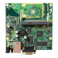
Jumper Index
J1 Although marked on the board as to select CPU frequency, it has no real effect and, thus, not
populated on the production boards. Use the boot loader to configure CPU speed
JP1 User-defined jumper (GPIO3 / CTS signal – only useful when serial port is not used)
JP2 Serial port autopower-off and software-controlled operation
Open Normal operation with autopower-off enabled
Closed Force on
JP3
JP4
Input voltage select
1-2 48V mode (25..56V DC)
2-3 12V mode (6..22V DC)
JP5
JP6
Power source select
1-2 Power jack/header
2-3 Power over Ethernet
JP7 IEEE802.3af Power over Ethernet standard operation
Open Normal operation according to IEEE802.3af Power over Ethernet standard
Closed Disable PoE control (for passive PoE injectors)
Button Index
S1 During the bootloader initialization, sets the default (266MHz) CPU frequency (see the
RouteBOOT section for more details). User-defined button (GPIO1 / RxD signal – only useful
when serial port is not used)
S2 Force immediate reboot
Ethernet Cables
RJ45
Pin
Color Function RJ45 pin for Straight cable
(MDI, EIA/TIA568A)
RJ45 pin for Crossover cable
(MDI-X, EIA/TIA568B)
1 Green TX+ Data 1 3
2 Green/White TX- Data 2 6
3 Orange RX+ Data 3 1
4 Blue - 4 4
5 Blue/White - 5 5
6 Orange/White RX- Data 6 2
7 Brown - 7 7
8 Brown/White - 8 8
Full Serial Null-modem (Console) Cable
DB9f Function DB9f DB25f
1 + 6 CD+DSR 4 20
2 RxD 3 2
3 TxD 2 3
4 DTR 1 + 6 6 + 8
5 GND 5 7
7 RTS 8 5
8 CTS 7 4
14
 Loading...