5
millnorway.com
EN
Description of heater
MILL INVISIBLE MILL GLASS
A B
Assembly
2. Wall bracket
1. On/Off 1. On/Off
3. Temperature sensor
4. Heat emission
5. Thermostat
6. Steel front
2. Wall bracket
3. Temperature sensor
4. Heat emission
5 Thermostat
6. Glass front
Drill holes in the wall for holes 1 & 2. Then drill holes in the wall for the topmost holes
(holes 3 & 4 by using 6)
Insert the wall plugs into the drilled holes and attach the bracket with 4 screws
Place the heater on the lower lugs on the bracket, then hang the heater on the
upper lugs (lift the heater slightly to align the heater with for the upper lugs). Screw
in the locking screws on the top of the bracket (clockwise)
Attention! Horizontal placement only
Temperature calibration
Power Indicator
See figure 4 on separate illustration sheetf
It may occur deviation between the temperature registered by the heater and the
If the heater uses power (for example, when it heats up), the power indicator is on.
First use
After turning on the heater for the first time or after an extended period without use,
the heater can produce a burnt odor for a short time. This is normal.
Please read all the instructions carefully before use. Save the instruction manual for future use.
It is also normal for the heater to make “sounds” when it warms up or cools down.
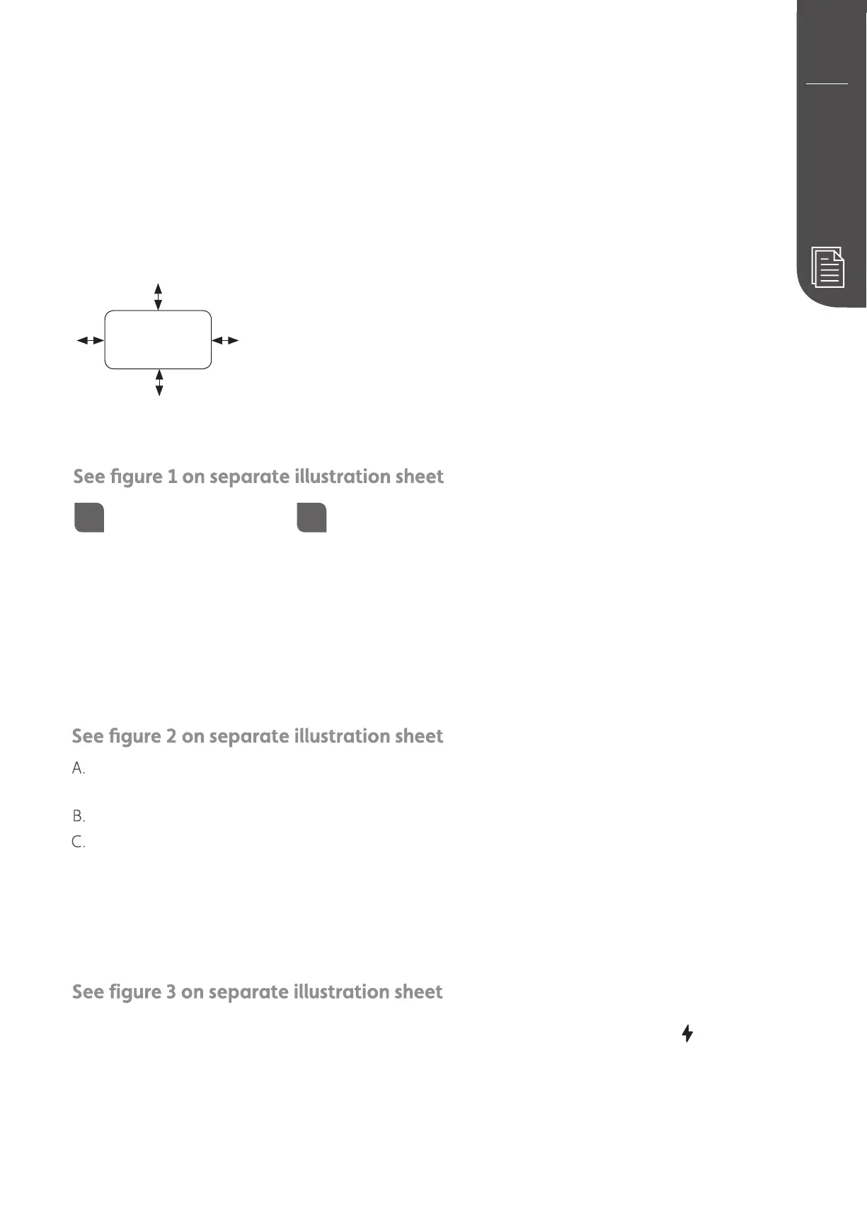
≥100 mm
≥50 mm≥50 mm
≥100 mm
≥100 mm in front
of heater
Minimum distances
 Loading...