. A complete Parts List is available at www.MillerWelds.com
OM-624 Page 8
SECTION 5 − INSTALLATION
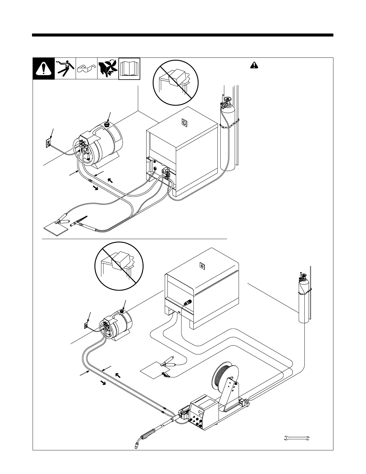
5-1. Connections
160 556-A / 160 555-C
! Do not move or operate unit
where it could tip.
To prevent overheating, make sure
cooling unit is positioned so airflow
is not restricted.
NOTICE − If welding power source
has a water valve, do not connect
hoses to water valve. Connect
hoses as shown.
1 Filler Cover
2 Coolant Out
3 Coolant In
Fittings have 5/8-18 left-hand
threads.
See Section 4-3 to select proper
coolant, and fill tank. Maintain cool-
ant level at approximately 1 in. (25
mm) from filler neck.
4 115 Volt AC Grounded Re-
ceptacle
Unit turns On when plugged in.
An individual branch circuit capable
of carrying 15 amperes and pro-
tected by fuses or circuit breakers
is recommended. Recommended
fuse or circuit breaker size is 15
amperes.
GTAW Connections
GMAW Connections
1
2
3
4
Tools Needed:
5/8 in.
1
2
3
4