Service Connections
PELLERIN MILNOR CORPORATION
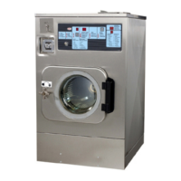
Figure 1: Correct Rotation During
Drain and Extract (when viewing
front of machine)
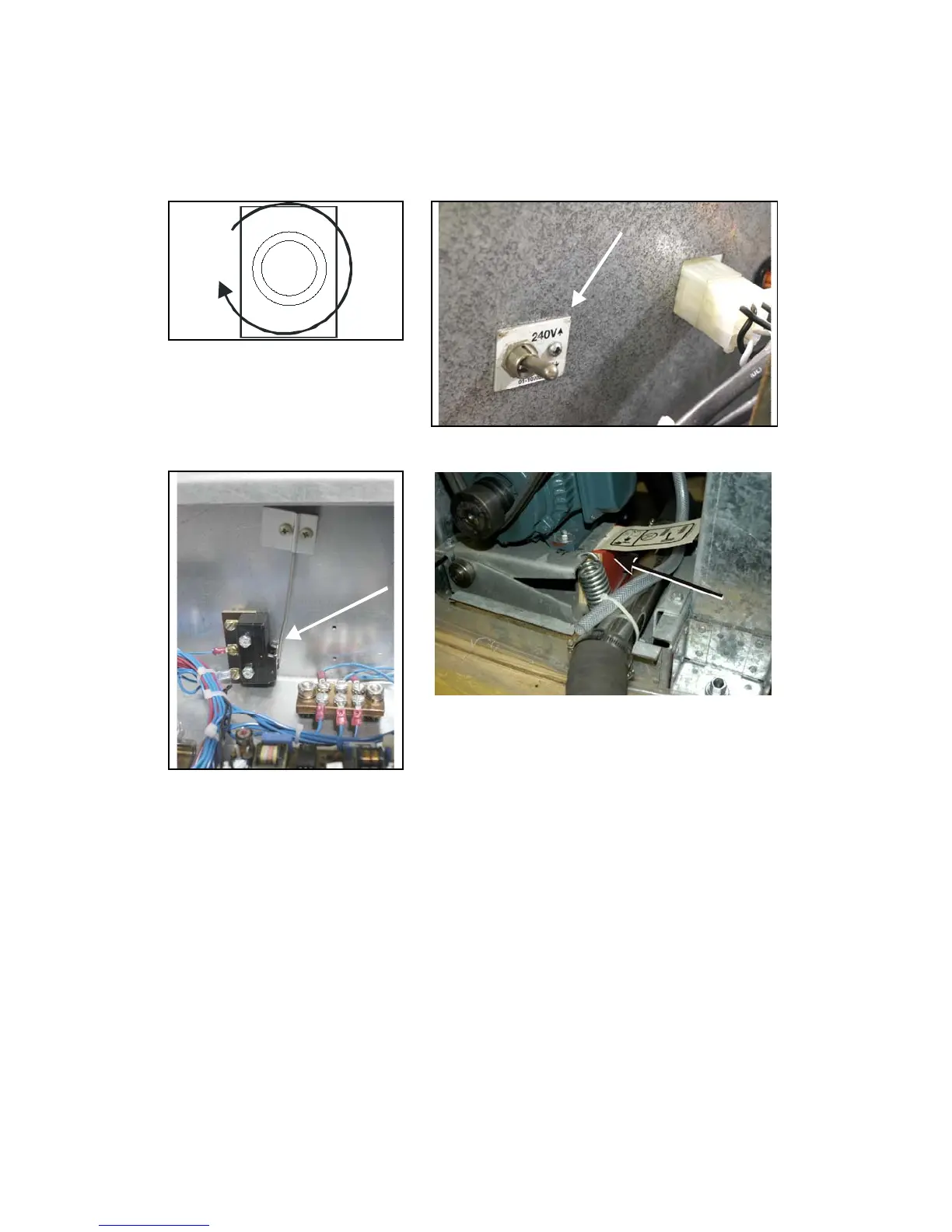
Figure 2: Line Voltage Switch
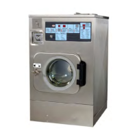
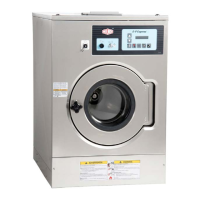
Figure 3: Vibration Switch Figure 4: Motor Mount Blocking
6. Remove Shipping Restraints
Remove all shipping restraints (usually marked in red). Restraints may be located behind access
panels. Restraints may include the vibration switch (Figure 3) restraint, motor mount blocking
(Figure 4).
7. Check Cylinder Surface
Check the perforated cylinder for smoothness. Milnor will not accept responsibility for the
cylinder finish after the machine is placed in service.
— End of BIRQVI01 —