The document describes the Cable Junction Box PR 6130/65S manufactured by Minebea Intec. This device is designed for tank and hopper weighing applications and can also be operated in potentially explosive atmospheres.
Function Description
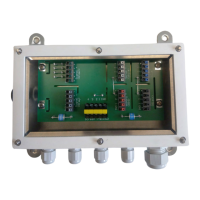
The cable junction box serves as an interconnection point for multiple load cells (up to 8) and an evaluation unit (e.g., an indicator). It facilitates the connection of various load cells to their interfaces, ensuring proper signal transmission and, where applicable, intrinsic safety in hazardous environments. The device is equipped with jumpers for corner correction resistors, allowing for electronic corner correction to compensate for mechanical imbalances and ensure accurate weight readings.
For load cells with 4-wire cables, jumpers J1 and J2 must be soldered in. The device also supports connections for 6-wire cables. The internal electronics manage the signals from the load cells and transmit them to the downstream device. The housing is designed for robust industrial use, including protection against ingress of dust and water.
Important Technical Specifications
General:
- Installation Position: Cable entry from below.
- Quantity of Load Cells: 1 to 4 (for PR 6130/65S, the image shows 8 terminals for load cells, implying support for up to 8).
- Clamping Area Screw Connection M12: 4.5–6.5 mm.
- Clamping Area Screw Connection M16: 5–9.5 mm.
- Pressure Equalization: Stainless steel pressure equalization element.
- Material of the Junction Box: High-grade stainless steel 1.4301 (X5CrNi 18-10) according to EN 10088-3, AISI 304, JIS SUS304.
- Surface of the Junction Box: 2R according to DIN EN 10088-2 (cold-rolled, bright annealed, flat, blank, reflective).
- Net Weight: 0.63 kg.
- Shipping Weight: 0.88 kg.
- Service Temperature Area: -30 °C to +80 °C.
- Service Temperature Area in Explosion-Prone Area: -20 °C to +60 °C (varies by model and certification, e.g., -40°C to +60°C for PR 6130/68S-Temp).
- Storage Temperature Range: -30 °C to +80 °C.
- Cable Screw Connections: Metal Ex EMC cable screw connections, brass CuZn39Pb3, galv. nickel-plated.
- Insulation Impedance (in service temperature range at 95% air humidity and Upc = 500 V): >1000 MΩ.
- Ingress Protection: IP64 (minimum), IP66, IP67, IP68, IP69 depending on the specific model.
- Maximum Voltage (non-intrinsically safe applications): Umax = 25 V.
- Minimum Load Cell Resistance: 300 ohms per load cell.
- Maximum Surface Temperature (non-intrinsically safe applications): T50 °C at Ta (40 °C) and T70 °C at Ta (60 °C).
Electromagnetic Compatibility (EMC):
- Housing: High frequency electromagnetic fields EN 61000-4-3 (80...3000 MHz) – 10 V/m.
- Electrostatic Discharge (ESD): EN 61000-4-2 – 6/8 kV.
- Signal and Control Lines:
- Fast transients (burst) EN 61000-4-4 – 1 kV.
- Peak voltages (surge) 1.2/50 µs EN 61000-4-5 – 1 kV.
- Conducted disturbances by high frequency coupling (0.15...80 MHz) EN 61000-4-6 – 10 V.
Ex-Protection Marking (examples from certificates):
- ATEX:
- II 1G Ex ia IIC T6/T4 Ga
- II 1D Ex ia IIIC T90°C Da
- II 2D Ex tb IIIC T50°C/T70°C Db
- II 3G Ex nA IIC T6 Gc
- IECEx:
- Ex ia IIC T6/T4 Ga
- Ex ia IIIC T90 °C Da
- Ex tb IIIC T50 °C/T70 °C Db
- Ex nA IIC T6 Gc
- FM Approvals (Canadian/US):
- IS CL I, II, III, DIV 1, GP A,B,C,D,E,F,G T4; 4X, IP6x
- NI CL I, DIV 2, GP A,B,C,D, T4; 4X, IP6x
- DIP CL II, DIV 2, GP E,F,G T4; 4X, IP6x
- CL I, Zone 0, Ex ia IIC T4; 4X, IP6x
- Zone 20, AEx ia IIIC T90°C; 4X, IP6x
Intrinsic Safety Parameters (Ex ia IIC/IIIC):
- Input Voltage (Ui): 25 V
- Input Current (Ii): See table below (e.g., 210 mA at 40°C for T6, 325 mA at 60°C for T4, 370 mA at 40°C for T4)
- Input Power (Pi): any
- Internal Capacitance (Ci): 0 nF
- Internal Inductance (Li): 0 µH
Usage Features
- Versatile Application: Suitable for tank and hopper weighing, including in potentially explosive atmospheres (Zones 0, 1, 2, 20, 21, 22, and Divisions 1, 2).
- Load Cell Compatibility: Designed for use with a wide range of Minebea Intec load cells (e.g., PR 6201, PR 6202, Inteco®, PR 6207, PR 6212, PR 6241, Contego®, PR 6246, PR 6251, Novego®, MP 55, MP 58(T), PR 40, PR 43, PR 47, PR 76, MP 77, MP 79(T)). Specific load cells are listed as "to be used" and "not to be used" for different applications.
- Electronic Corner Correction: Supports the integration of resistors (0-5.6 ohms, 1%, type MBB0207, P70 = 0.6W) for electronic corner correction, which can be adjusted by trained technicians in non-hazardous locations. This feature helps align the displayed value of each load cell with a reference cell.
- Robust Construction: Stainless steel housing with high IP ratings (IP64 to IP69) ensures durability and protection in harsh industrial environments.
- Cable Management: Features M12 and M16 cable glands for secure and leak-tight cable entry, accommodating various cable diameters. Wires should be fitted with wire end ferrules for optimal connection.
- Equipotential Bonding: All metal parts (housing, load cells) must be electrically connected to an equipotential bonding conductor (PA) using an earth cable of at least 4 mm² cross-section.
Maintenance Features
- Repairs: All repairs must be carried out by Minebea Intec or authorized service personnel. In case of defect, contact the local Minebea Intec dealer or service center.
- Soldering Work: Soldering is permitted on the device specifically for corner correction. This should be done by a suitably trained technician in a non-hazardous location.
- Cleaning:
- Disconnect the device from the mains supply and data cables before cleaning.
- Clean with a cloth lightly moistened with a soap solution.
- Wipe dry with a soft, dry cloth.
- Precautions: Prevent moisture from penetrating the interior. Do not use aggressive cleaning agents (solvents) or unsuitable cleaning utensils. For food industry applications, use a suitable cleaning agent.
- Initial Inspection: Before operational startup and after storage or transport, a visual inspection for mechanical damage is required.
- Regular Checks: Regularly check the fitted cable glands for tightness and re-tighten if necessary.
- Installation Checks: At reasonable intervals, the equipment installation should be checked for proper functioning and safety by a trained and certified technician.
- Genuine Parts: Only genuine replacement parts supplied by the manufacturer should be used for repairs.
- Modifications: Any modifications to the equipment require express written authorization from Minebea Intec.