144
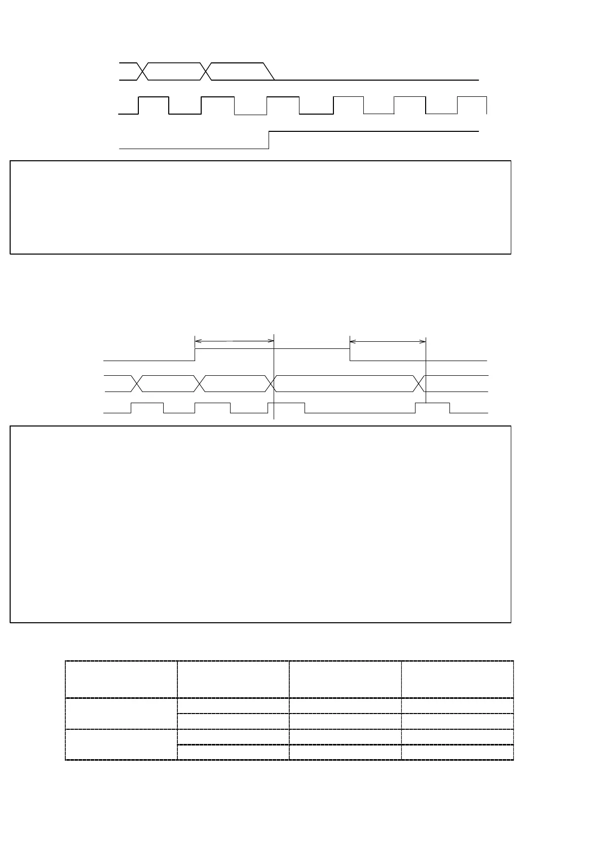
(3) When ERROR is occurred
DATA
POL.
P.C.
ON
ERROR
ON
ONON ON ONON
● At the time of ERROR output, output transistor at ERROR signal
will become ON(Negative logic electrically). Moreover, for each DATA,
POL., all of the output transistor will become OFF at the time of
ERROR output(Positive logic electrically).
(4) When the HOLD signal is input
4 times/s:Approx. 250 ms at max.+Input response time
20 times/s:Approx. 50 ms at max.+Input response time
DATA
POL
P.C.
HOLD
ON
50 times/s:Approx.20 ms at max.+Input response time
100 times/s:Approx.10 ms at max.+Input response time
4 times/s:Approx.250 ms at max.+Input response time
20 times/s:Approx.50 ms at max.+Input response time
50 times/s:Approx.20 ms at max.+Input response time
100 times/s:Approx.10 ms at max.+Input response time
200 times/s:Approx.5 ms at max.+Input response time 200 times/s:Approx.5 ms at max.+Input response time
● At the time of HOLD signal input, output transistor for the P.C. will
be OFF condition. (Positive logic electrically.)
● After inputting the HOLD signal, it takes the following response
times to freeze the DATA, POL or cancellation of HOLD is executed.
At 200 times/s:Approx.5 ms at maximum+Input response time
At 100 times/s:Approx.10 ms at maximum+Input response time
At 50 times/s:Approx.20 ms at maximum+Input response time
At 20 times/s:Approx.50 ms at maximum+Input response time
At 4 times/s:Approx.250 ms at maximum+Input response time
9−2−6. Output condition
Condition of
Pin−COM level
ett
n
output
og
c
utput
at
transistor
tt
time o
vo
tage
supply externally.
Yes ON L
egat
ve
og
c
No OFF H
Yes OFF H
os
t
ve
og
c
No ON L


 To Next Page
 Loading...