6
4. Connecting method
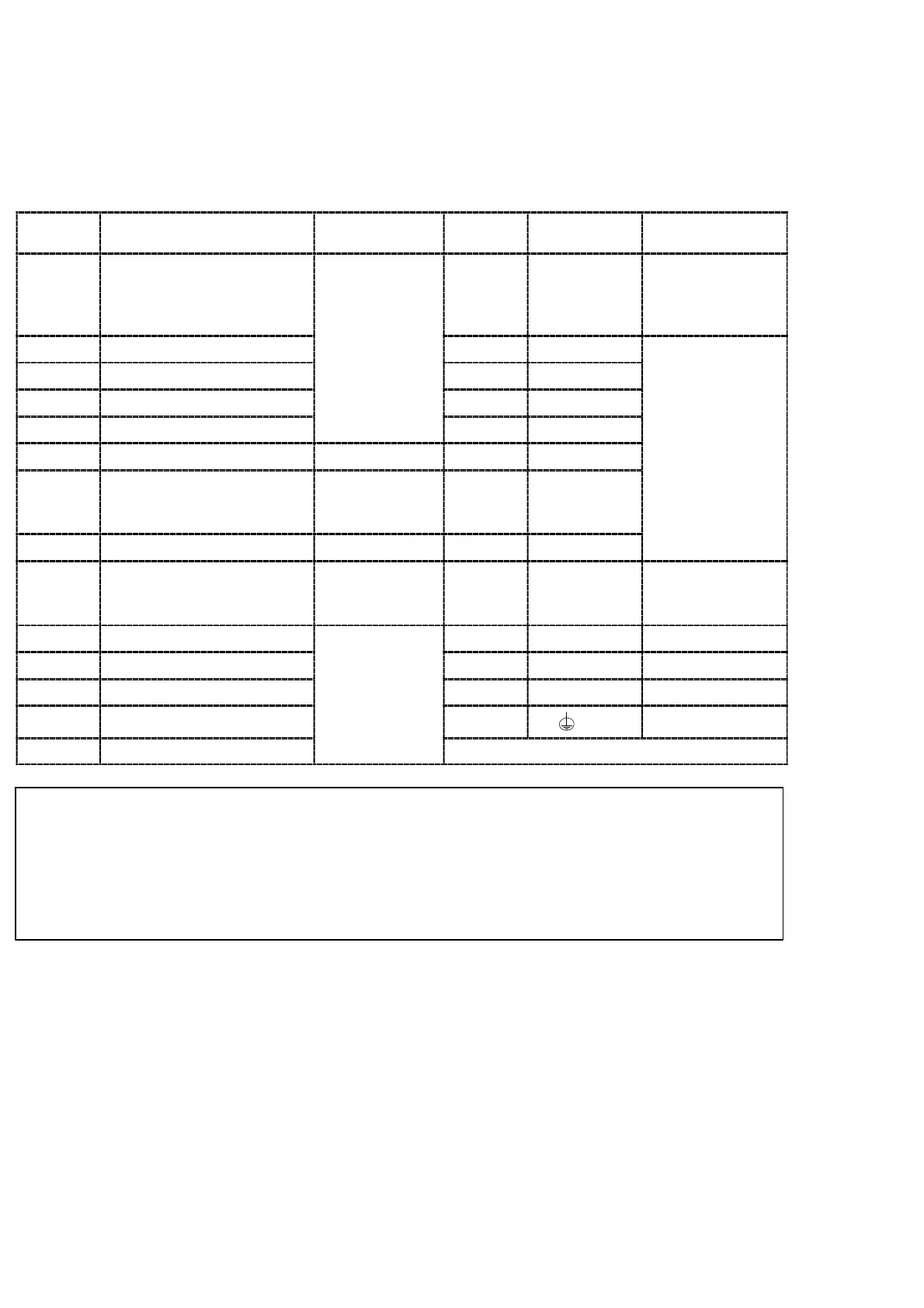
4−1. Layout of the terminal boards
There is the terminal boards, which has 27 points of terminals.
Layout of terminal boards are shown in the following figure.:
Terminal
No.
Descriptions Applications
Terminal
No.
Descriptions Applications
1 E(Shield)
15 COM.
Common for
external control
input and open
collector output
2 D(Amplifier input +)
applied
16 RUN
3 A(Bridge power supply +)
transducer
17 ERROR
4 B(Amplifier input −) 18 SO
5 F(Sensing +) 19 S1 Open collector
6 A−OUT + Analog output 20 S2
output
7 G(Sensing −)
Strain gage
applied
transducer
21 S3
8 A−OUT − Analog output 22 S4
9 C(Bridge power supply −)
Strain gage
applied
transducer
23 N.C.
10 ZERO 24 SOURCE AC power supply
11 HOLD 25 N.C.
12 A/Z
External
26 SOURCE AC power supply
13 A/Z OFF
con
ro
ou
pu
27 Ground
14 LOCK
● The COM.(Terminal No.15) is common for the external control input
(Terminal No.10〜14) and the open collector output(Terminal No.16
〜22).
● Don’t connect with N.C. terminals(Terminal No.23 and 25).