⑬
4.
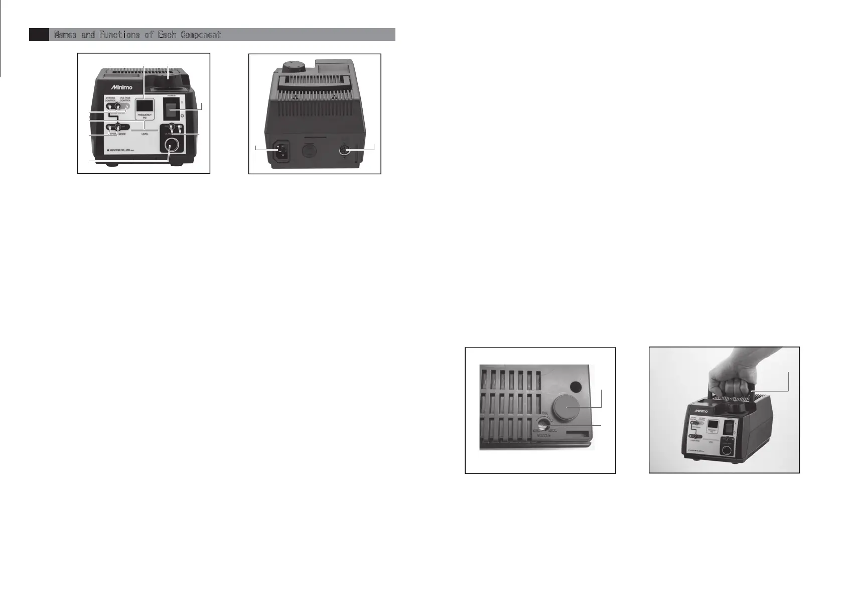
Names and Functions of Each Component
5 6
①Main Switch
To perform ON/OFF of the main power source(l:ON ○:OFF)
②Display
Vibration frequency is indicated when operating handpiece and error content is indicated when occurring error.
◆Handpiece in stop …… Lights-out
◆Handpiece in operation …… Indicating vibration frequency of handpiece in kHz.
③Level Light
LEDs are lighted from the left side proportionally to amplitude amount of handpiece.
◆Handpiece in stop …… Number of lighted LED is increased/decreased proportionally to the position of
indicator on power control knob.
◆Handpiece in operation …… Number of lighted LED is increased/decreased proportionally to the vibration
frequency.
④Power Controlling Knob
◆On STROKE CONTROL …… For setting of amplitude amount.
◆On VOLTAGE CONTROL …… For setting of drive voltage.
⑤DRIVE MODE Switch ・ STROKE CONTROL Light ・ VOLTAGE CONTROL Light
For setting drive mode of handpiece.
◆STROKE CONTROL …… Driving with fixed amplitude amount.
◆VOLTAGE CONTROL …… Driving with constant voltage.
※Select drive mode while handpiece is NOT in operation. Unable to select drive mode while handpiece is in operation.
The lamp of set drive mode is lighted.
Error number will be indicated on display while pressing the switch when error occurred.
⑥POWER MODE Switch ・ POWER MODE Light
Setting ON/OFF of POWER MODE (on STROKE CONTROL mode only).
LED light is on while POWER MODE is activated.
If POWER MODE was activated, maximum drive voltage is increased and power to sustain amplitude amount becomes
stronger.
※POWER MODE switch does not work on VOLTAGE CONTROL mode.
※POWER MODE switch is always off when turning on the main power supply switch.
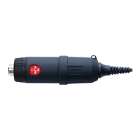
⑦ULTRA SONIC ON/OFF Switch・ULTRA SONIC Output Light
To use and control On/Off of a handpiece
Pressing the ULTRA SONIC On/Off switch will run a handpiece and then pressing the switch again stop the handpiece.
The colors of the ULTRA SONIC output light indicate the followings:
Light-Off - Handpiece is in stop.
Blue - Handpiece is in operation.
Red - Errors occur
⑧ULTRA SONIC Socket
Sockets for the plug of a handpiece to be connected
⑨AC Socket
Use the right cable for the right power pack
⑩Foot Switch Socket
The socket for the plug of foot switch
⑪Buzzer Trimmer
To adjust volumes of switch operation sound, switch operation no-effect sound, and error sounds.
Use a Phillips head screwdriver to adjust the volumes. ( Clockwise for volume up, counterclockwise for volume down)
◆Error sounds
●Switch operation sound - one pip sound ●Switch operation no-effect sound - two pip sounds
●Error sounds - continuous pip sound
⑫Tapped Hole for Fixing Power Pack
Powerpack has φ3.2mm holes under the rubber legs.In order to fix a powerpack, remove the rubber legs and use
self-tapping screws (M4).Use the self-tapping screws (M4) with its insertion length under 15mm to the powerpack.
⑬Carrying Handle
Retractable handle for carrying a power pack
fig-2 fig-3
fig-4
fig-5
⑫
⑪
Frontside
Backside
Base
①
②
③
④
⑤
⑥
⑧
⑦
⑩
⑨