EasyManua.ls Logo

Mirage B-310-G User Manual

Mirage B-310-G
9 pages
To Next Page IconTo Next Page
Page #1 background imageLoading...
Page #1 background image
Mirage B-310-G Instruction Manual
1
Mirage B-310-G
The Mirage B-310-G is a VHF power amplifier designed for the
144-148 MHz band. New features make it the most useful and
versatile amplifier available for the handheld transceiver.
Features include all mode compatibility (FM/SSB/CW), wrap-
around heat sink, high gain GaAsFET preamplifier, and 25O mW
to 8 watts input.
FEATURES
1. High output power of 100 watts
100 watts is achieved with 250 mW to 8 watts input.
2. All mode compatibility (FM/SSB/CW)
In the SSB mode the time constant of the Carrier
Operated Transmit (COX) relay is set to approximately
one second to prevent annoying relay chatter
during conversation, and achieving smooth SSB
transmission.
3. Wrap-around heat sink
The heat sink and combined case, by original design
is used for excellent heat dissipation as well as a
new smart appearance.
4. Input power from 250 mW to 8 watts
With an input power of 8 watts maximum, the Mirage
B-310 -G is compatible with most modern handheld
transceivers.
5. GaAsFET receive pre-amplifier
A built-in low noise GaAsFET receive pre-amp enables you
to enjoy a more comfortable VHF QSO with weak
stations.
Question and Answer IconNeed help?

Do you have a question about the Mirage B-310-G and is the answer not in the manual?

Mirage B-310-G Specifications

General IconGeneral
BrandMirage
ModelB-310-G
CategoryAmplifier
LanguageEnglish

Summary

Mirage B-310-G Product Overview

Key Features

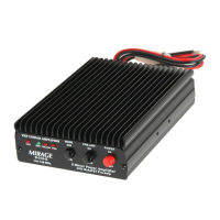
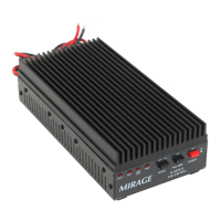
Highlights 100W output, all-mode, heat sink, GaAsFET pre-amp, and input power range.

Specifications

Front Panel Indicators

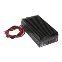
Details front panel indicators like XMIT, SWR, PRE-AMP, and PWR LEDs.

Front Panel Controls

Mode and Power Switches

Describes front panel controls including MODE, PRE-AMP, and POWER switches.

Back Panel Connections

Back Panel Ports

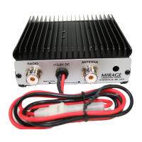
Details Antennna, +13.8V DC, Radio, and External Keying connectors on the back panel.

Installation

Mounting and Ventilation

Provides instructions for mounting the amplifier and ensuring adequate ventilation for the heat-sink.

Wiring and Operation

Wiring and Power Considerations

Explains DC power connection, wire gauge, voltage limits, and antenna system SWR recommendations.

Troubleshooting

Common Troubleshooting Steps

Lists common problems like connections, SWR, power supply, and fuse issues to check before assuming malfunction.

Technical Assistance

Contact and Support Information

Provides contact information for technical support via phone and FAX, including recommended information to provide.

Block Circuit Diagram

Amplifier Block Circuit Overview

Illustrates the internal signal flow of the booster amplifier with key components like RX, TX, and relay controller.

Schematic Diagram

Circuit Schematic

Presents the detailed electronic schematic of the Mirage B-310-G amplifier.