EasyManua.ls Logo

Mirage B-320-G User Manual

Mirage B-320-G
10 pages
To Next Page IconTo Next Page
Page #1 background imageLoading...
Page #1 background image
Mirage B-
320
-G Instruction Manual
-1-
Mirage B-320-G
The Mirage B-320-G is a VHF power amplifier designed for 2
meters covering 144-148 MHz. The “Hi” and “Lo” input selector
switch makes this amp useable for both handheld and mobile
transceivers. Features include all mode compatibility
(FM/SSB/CW), wrap-around heat sink, high gain GaAsFET
preamplifier, and user selectable input:
--”Lo” for Handheld radios-- 250 mW to 10 Watts
--”Hi” for Mobile radios-- 10 Watts to 50 Watts
FEATURES
1. High output power of 200 watts
200 watts is achieved with 250 mW to 10 Watts input
on “Lo” or 10 Watts to 50 Watts input on “Hi”.
2. All mode compatibility (FM/SSB/CW)
In the SSB mode the time constant of the Voice
Operated Transmit (VOX) relay is set to approximately
one second to prevent annoying relay chatter
during conversation, and achieving smooth SSB
transmission.
3. Wrap-around heat sink
The heat sink and combined case, by original design
is used for excellent heat dissipation as well as a
new smart appearance.
4. “Lo” Input power from 250 mW to 10 Watts
With an input power of 10 Watts maximum on “Lo” , the
Mirage B-320-G is compatible with most modern
handheld and mobile transceivers.
5. “Hi” Input power from 10 Watts to 50 Watts
Question and Answer IconNeed help?

Do you have a question about the Mirage B-320-G and is the answer not in the manual?

Mirage B-320-G Specifications

General IconGeneral
BrandMirage
ModelB-320-G
CategoryAmplifier
LanguageEnglish

Summary

FEATURES

High output power of 200 watts

Achieves 200W output with specified input power levels.

All mode compatibility (FM/SSB/CW)

Supports FM, SSB, and CW modes with optimized relay timing for SSB.

Wrap-around heat sink

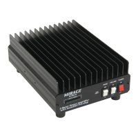
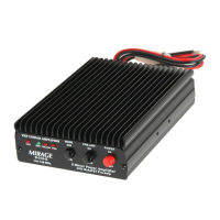
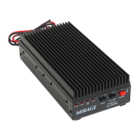
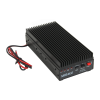
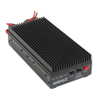
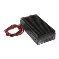
Features an integrated heat sink and case for effective heat dissipation.

"Lo" Input power from 250 mW to 10 Watts

Compatible with handheld transceivers using low input power.

"Hi" Input power from 10 Watts to 50 Watts

Compatible with mobile transceivers using higher input power.

GaAsFET receive pre-amplifier

Includes a low-noise GaAsFET pre-amplifier for improved reception.

EXPLANATION OF FEATURES

OUTPUT POWER LED

Indicates the output power status of the amplifier.

MODE LED

Displays the selected operating mode, SSB or FM.

PRE-AMP LED

Illuminates when the receive pre-amplifier is active.

PWR LED

Shows if the amplifier is in standby or bypass mode.

SWR Fault LED

Alerts the user to a high SWR condition.

MODE (SSB/FM) SWITCH

Selects operating mode to adjust relay timing for SSB/CW.

PRE-AMP (ON/OFF) SWITCH

Engages or disengages the receive pre-amplifier.

POWER (ON/OFF) SWITCH

Controls the main power supply to the amplifier.

BACK PANEL

INPUT POWER SWITCH

Controls the input power to the unit.

RADIO CONNECTOR

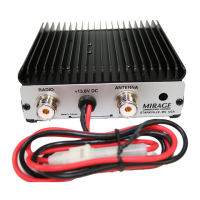
Coaxial connection for the transceiver's output.

+13.8V DC INPUT

Connection point for the DC power supply.

FUSE HOLDER

Houses the protective fuse for the unit.

ANTENNA CONNECTOR

Coaxial connection for the antenna.

INSTALLATION

Mounting and Ventilation

Guidelines for physical mounting and ensuring adequate airflow.

Wiring and Operation Guidelines

Instructions for DC power wiring and antenna system setup.

TROUBLESHOOTING

Common Issues and Checks

Lists common problems and initial checks before assuming a malfunction.

TECHNICAL ASSISTANCE

Contacting Support

Information on how to get help from Mirage support.

ONE YEAR LIMITED WARRANTY

Warranty Terms and Conditions

Outlines the terms, coverage, and process for warranty service.

SCHEMATIC

Circuit Diagram

Provides the electrical schematic of the amplifier.