Do you have a question about the Mission 734 and is the answer not in the manual?
Guidance on connecting loudspeakers, including conventional, bi-wiring, and bi-amping.
Advice on optimal room placement for best sound stage and bass extension.
Definition and importance of dynamic range in audio reproduction.
How loudspeakers reproduce and control musical speed and attack.
Load characteristics presented to the amplifier and phase shift considerations.
Ability to accept electrical inputs without distortion or damage.
This document is an instruction manual for Mission Loudspeakers, providing comprehensive guidance on their setup, connection, positioning, maintenance, and technical aspects.
Mission Loudspeakers are precision-manufactured audio products designed to reproduce music with exceptional realism and high fidelity. They are engineered using advanced computer-controlled technology to deliver a smooth, accurate, and balanced sound across the audio frequency band. The loudspeakers are designed to be an integral part of a hi-fi system, transforming electrical energy into mechanical energy to create a three-dimensional stereo sound stage with correct instrument size and position. They are optimized for wide dynamic range musical reproduction, preserving power response linearity throughout the dynamic range and allowing the reproduction of large transients while maintaining quality at the lowest levels. The design also focuses on minimizing coloration, which refers to various distortions and aberrations that can occur in loudspeakers, including both 'additive' and 'subtractive' distortions. The drive units are 'Direct Coupled' to substantial baffle boards made of special materials, and the enclosures are precision-designed and visco-elastically damped to reduce unwanted acoustic output and eliminate internal standing waves. The driver membranes are made of special, rigid, and acoustically opaque materials with optimized mathematical profiles and mechanical terminations, ensuring smooth performance with controlled break-up modes and minimal resonances.
Running-In Period: For optimum performance, the loudspeakers should be run in for a period of 10 hours before final positioning. This allows the sophisticated drive units to settle and achieve their best sound quality.
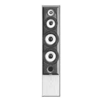
Use of Spikes: Floorstanding models are supplied with stabilising spikes for better coupling to the floor. Turn the loudspeaker upside down on a soft surface. Screw on the nuts, fit washers between the nut and the bush, then screw spikes into the bushes. Ensure each spike is screwed in approximately the same distance for easier levelling. Turn the loudspeaker over, place in position, and adjust spike height until stable and perfectly upright. Tighten locknuts without overtightening.
Use of Rubber Feet: For delicate flooring like parquet, rubber feet are supplied as an alternative to spikes.
Sandfilling the Base (Mission 733 only): The lower chamber of the Mission 733 speaker is an integral stand and can be filled with dense material like lead shot or dry sharp/silver sand (not builders' sand) for improved performance. Remove the plastic bung from the rear, push the supplied plastic bag through the hole, and tie a knot. Using a funnel, pour dry sand/shot into the bag, shaking the speaker slightly to settle the sand. Fill until just below the hole, tie a knot, push the end into the cavity, and replace the bung. Ensure sand is completely dry and never put sand directly into the cabinet.
Ancillary Equipment: The quality of your amplifier, compact disc player, turntable, arm, and cartridge significantly impacts performance. High-quality equipment, not necessarily expensive, is recommended. Mission recommends Cyrus amplifiers. Choose amplifiers with minimal gimmicks and controls.
Cleaning: Mission loudspeakers are treated with a special sealant, making regular polishing unnecessary. Frequent wax polishing can darken and dull the finish. Use a lightly dampened soft cloth for cleaning. Occasionally, use a household spray polish applied first to a soft polishing cloth (away from the drive units) to restore sheen. If cleaning the grille, remove it first and brush gently with a soft, clean brush.
Drive Units: There are no user-serviceable parts inside the loudspeaker; the drive units are gasket sealed for life. Avoid dismantling the loudspeaker, as this will void the warranty. It is important for mid/bass drive units to be rigidly fixed. Occasionally tighten the fixings on the bass driver only. Do not touch high-frequency drive unit fixings.
Faults: If a fault occurs, return both loudspeakers as a pair, even if only one appears faulty. Use original packing materials for safe transit.
Guarantee Conditions: The guarantee is effective if completed by the Dealer and Purchaser and returned to Mission or their Distributor within 8 days of purchase. It excludes damage from accident, misuse, wear and tear, neglect, incorrect installation, adjustment, or repair, and liability for damage or loss during transit. Claims should be made through the Dealer. Mission is not liable for consequential damage. The Purchaser bears carriage costs. The guarantee is personal and non-transferable. Mission reserves the right to charge for examination and return carriage if equipment complies with specifications. Unauthorized servicing voids the guarantee. Retain a copy of your sales receipt for returns. These conditions do not affect statutory rights.