FRONT PANEL CONFIGURATION
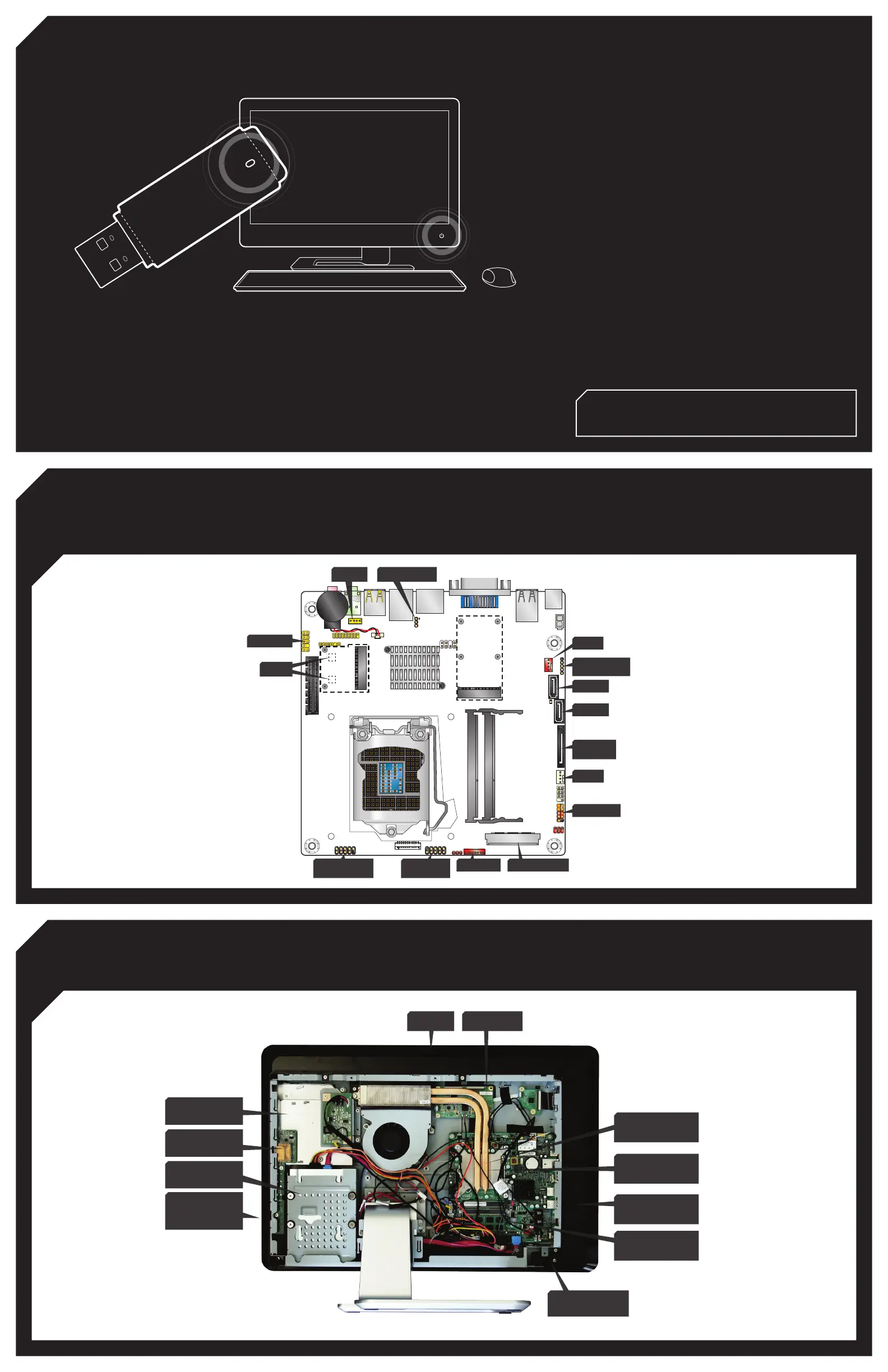
CONNECTING CABLES TO THE INTEL® DESKTOP BOARD DH61AG
SYSTEM OVERVIEW
(ALL CABLES ARE LABELED TO SUPPORT
QUICK CONFIGURATION)
CARD READER
(DUAL PORT USB HEADER)
DUAL PORT
USB HEADER
FPD POWER LVDS CONNECTOR
SWITCH CABLE
CPU FAN
HDD SATA
ODD SATA
SYS FAN
SPEAKER
BIOS-CFG JUMPER
USB HEADER FOR
CAMERA CABLE
SATA POWER
(HDD + ODD)
AUDIO CABLE
AERIAL
USB and Audio
Connectors
LGA 1155
Processor Socket
SO DIMMS
MMC / SD Card
Slot
2.5 Inch SATA or
Solid-State Drive
Intel® Thermal
Solution
Webcam Touch Panel
Slimline Optical
Disc Drive
Power and
Brightness
Controls
Internal Speakers
Integrating the Intel® Desktop Board DH61AG
Revision G23736-503
This desktop board revision ships with LVDS disabled, therefore the system
BIOS must be updated in order to enable the flat panel display. Perform the
following steps to update the system BIOS via the BIOS Recovery process.
Remove the yellow jumper from the BIOS_CFG header (located next to the
RJ-45 jack behind the backpanel) - refer to desktop board diagram in this
document.
Copy AG0043P.BIO (or the latest BIOS version*) to the root level of a USB
flash drive and attach it to any of the available USB ports.
Please Note: It may be useful to use a USB flash drive that has an LED
indicating drive activity to observe part of the update process.
Power on the system and wait approximately 1m 30s for the BIOS Recovery
update to complete; during this time the blue system power LED:
will start flashing shortly after 15 seconds
will stop flashing at around 1 minute 30 seconds (it is good practice to
wait an additional 5 seconds after the blue system power LED stops
flashing before proceeding)
Power off the system and remove the AC adapter from the backpanel DC
jack; the USB flash drive may also be removed at this time.
Restore the yellow jumper onto the BIOS_CFG header pins 1-2 (closest to
backpanel).
Reconnect the AC adapter into the backpanel DC jack.
Note: It is normal behavior for a short false start to be observed upon the very
first boot after the BIOS Recovery process.
Once this step is complete, continue with the steps outlined in the section titled
"Integrating the Intel® Desktop Board DH61AG revision G23736-504 (or later)".
This desktop board revision ships with LVDS enabled at the factory for
generic 1920x1080/dual-channel/24bpp panels. Perform the following
steps to select optimal panel timings for the Thin mini-ITX All-in-One chassis.
Power on the system and press F2 to enter BIOS Setup when the flat
panel display shows the Intel splash screen
Navigate to the Configuration | Video page
Set “All-in-One Chassis” to the appropriate chassis.
Set “Flat Panel Configuration Changes” to <Locked>
Note: Once a flat panel configuration is locked it can only be unlocked from
this page when booting in BIOS Maintenance mode (BIOS_CFG pins 2-3) or
using the Intel® Integrator Toolkit utility.
This step is strongly recommended in order to prevent potential end-user
tampering with panel settings that may result in loss of video configuration.
Press F10 to save settings and exit BIOS configuration
Integrating the Intel® Desktop Board DH61AG revision G23736-504 (or later)
1.
2.
3.
4.
5.
1.
2.
3.
4.
5.
6.
a.
b.
* Navigate to the Intel® Desktop Board DH61AG support page to download the latest
BIOS version: http://www.intel.com/p/en_US/support/highlights/dsktpboards/db-dh61ag
 Loading...