EasyManua.ls Logo

Mitsubishi Electric BC16 - User Manual

Mitsubishi Electric BC16
23 pages
Print Icon
To Next Page IconTo Next Page
Loading...
Mitsubishi Electric Power Products, Inc.
BC16 Battery Cabinet
Installation, Operation, & Maintenance Manual
Built for Mitsubishi Electric Power Products, Inc. by
Question and Answer IconNeed help?

Do you have a question about the Mitsubishi Electric BC16 and is the answer not in the manual?

Summary

Important Information About This Manual

Manual Symbols

Explains warning, caution, and important symbols used in the manual for user safety and guidance.

Introduction

Safety Precautions

General Safety Guidelines

Covers reading the manual, regulations, qualified personnel, tools, PPE, and environmental considerations.

Electrical Hazard Warning

Highlights dangers of DC power, including shock, burns, fire, and potential death from system shorts.

Inspection Upon Receipt of Goods

General Inspection

Instructions for inspecting the entire shipment for damage upon receipt.

Visible Damage

Procedures for identifying and reporting visible external damage during transit.

Concealed Damage

Steps for checking for and reporting concealed damage within a specified timeframe after unpacking.

Return of Damaged Goods

Process for returning damaged equipment for repair, requiring an RMA number.

System Overview

System Specifications

Batteries

Details battery type (VRLA), voltage, and string configuration for the cabinet.

System Grounding

Specifies grounding requirements, including cabinet safety ground lug and wire sizing per NEC.

DC Output

Outlines DC output voltage, circuit breaker rating, and fuse type.

General Specifications

Provides cabinet dimensions, weight, operating temperature, and ventilation requirements.

Installation

Preparation

Steps to prepare for system installation, including inspection and safety review.

Installation Safety Precautions

Crucial safety precautions to review before starting system installation.

DC Voltage Warning

Critical warning about hazardous DC voltages and extreme caution needed during installation.

Installation Steps

Equipment Location

Guidelines for selecting an appropriate location with ventilation and temperature control.

Equipment Mounting

Instructions for moving and stabilizing the heavy battery cabinet using casters and leveling feet.

Equipment Grounding

Details on connecting the system ground wire from the main building source to the cabinet.

DC Connections

Procedures for making DC connections, including checking drawings, torque, and breaker status.

System Operation

Refers to the UPS manual for system start-up and operation details.

System Maintenance

Battery Replacement

Procedures for diagnosing, removing, and replacing malfunctioning batteries safely and correctly.

Battery Disposal Warning

Warnings about battery disposal, fire hazards, and contacting recycling centers.

Reference Materials

Warranty

Limited Warranty and Exclusions

Details the limited warranty period, exclusions, and remedies for product defects.

Overview

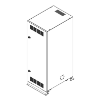
The Mitsubishi Electric Power Products, Inc. BC16 Battery Cabinet is a crucial component designed for uninterruptible power supply (UPS) systems, providing backup power during AC power failures. This installation, operation, and maintenance manual outlines the essential information for safely and effectively deploying and managing the BC16 Battery Cabinet.

Function Description:

The primary function of the BC16 Battery Cabinet is to house and protect valve-regulated lead-acid (VRLA) batteries, which serve as a backup power source for UPS systems. During normal operating conditions, the UPS charges these batteries to maintain their proper float voltage. In the event of an AC power failure, the batteries discharge to provide the necessary backup power to the connected load. It is critical to ensure that the batteries are not discharged below the manufacturer's recommendations and are recharged as soon as possible after any discharge event to prevent damage. The cabinet is designed to accommodate two 288 VDC battery strings, with each string comprising four trays of five 12 VDC batteries and one tray of four 12 VDC batteries.

Important Technical Specifications:

  • Cabinet Size: 19.70"W x 26.75"D x 55.12"H.
  • Empty Cabinet Weight: Approximately 375 lbs.
  • Battery Type: Valve Regulated Lead Acid (VRLA), sealed, non-spillable.
  • Battery Voltage (Nominal): 12 VDC per battery.
  • Battery String Voltage: 288 VDC per string. The cabinet supports two such strings.
  • Operating Temperature (Recommended): 20°C to 25°C (68°F to 77°F) for optimum battery performance.
  • Ventilation: The cabinet features ventilation slots in the front, rear, and top panels. A minimum clearance of four inches is required in front of and behind the cabinet to prevent obstruction of ventilation.
  • DC Output Voltage (Nominal): 288 VDC.
  • Circuit Breaker: UL Listed 600 VDC rated. Specific details are provided in the system drawings.
  • Battery Tray Fuse Type: Ferraz (Gould) A50QS, A50P, or equivalent.
  • System Grounding: Each cabinet includes a #14-1/0 mechanical ground lug, located on the lower right corner of the breaker pan, accepting bare wire from #6 AWG to 300 MCM cable. The torque for this connection is 325 lb-in. All system ground wires should be derived from the main building ground source and sized per NEC and/or applicable national and local codes.
  • Wire Size and Type: All internal wiring is UL Listed, MTW, Style, 105C, extra flexible cable. Ground wire and DC output wire sizes are specified per NEC and/or applicable codes, with DC output wires sized for a maximum voltage drop of 0.5 volts.
  • Battery Storage: Batteries should not be stored longer than three months at 25°C (77°F) or lower before recharging to prevent damage.

Usage Features:

  • Safety First: The manual emphasizes reading and understanding all safety precautions, system drawings, and schematics before installation or maintenance. Only qualified electricians or DC power technicians should install or service the equipment.
  • Tool Requirements: Installation requires heavily insulated hand tools and a digital voltmeter.
  • Heavy Equipment Handling: Battery cabinet systems are extremely heavy, requiring a minimum of two people for unloading and placement.
  • Mobility and Stability: The BC16 cabinet is equipped with four casters (two swivel in front, two rigid in back) for easy movement. Once in place, the front casters should be locked, and the four leveling feet at each corner lowered to stabilize the cabinet and prevent movement.
  • Environmental Considerations: Proper ventilation and cooling are essential. The cabinet should never be installed in a sealed enclosure due to the potential for batteries to vent explosive hydrogen gas.
  • DC Connections: Before making any DC connections to additional cabinets or the UPS, the output breaker must be in the off/open position, and the UPS charger must not be running. Internal battery connections should be checked and re-torqued upon receipt due to potential loosening during shipping.
  • External Disconnect: Battery cabinets not supplied with an incorporated DC output disconnect device must have an appropriate external disconnect device.
  • System Operation: Refer to the UPS system manual for detailed system start-up and operation information.

Maintenance Features:

  • Regular Inspections: Upon receipt, a thorough inspection for visible and concealed damage is required. Any damage or material shortages must be reported to the carrier and C&C Power, Inc.
  • Battery Replacement Procedure:
    1. Locate the shelf with the malfunctioning battery.
    2. Disconnect the UPS from the battery string by opening the circuit breaker in the battery cabinet.
    3. Remove the shelf from the cabinet.
    4. Test individual batteries to isolate the malfunctioning unit.
    5. Remove the retaining bar holding the batteries.
    6. Disconnect the malfunctioning battery.
    7. Prepare the new battery: verify it's the same type and amp-hour rating, measure battery voltage (should be 12.4 VDC or above), polish terminals with a brass wire brush or abrasive pad, and apply no-ox type terminal grease to prevent corrosion.
    8. Remove the old battery.
    9. Install the new battery, ensuring correct polarity orientation by referring to the wiring drawing inside the cabinet door.
    10. Reconnect cables and connecting bars to the installed battery, ensuring proper torque.
    11. Check the battery string voltage of the shelf (60VDC for shelves 1-4, 48VDC for shelf 5).
    12. Re-install the retaining bar.
    13. Re-install the shelf into the cabinet backplane.
    14. Check the battery string voltage at the input side of the circuit breaker.
    15. Reconnect the UPS to the battery string by closing the circuit breaker.
  • Battery Disposal: Batteries must not be disposed of in fire or regular trash. Contact local hazardous waste or recycling centers for proper disposal of sealed lead-acid batteries.
  • Warranty: C&C Power, Inc. provides a one-year limited warranty for repair or replacement of defective parts from the date of purchase. The warranty excludes incidental or consequential damages. Integrated products not manufactured by C&C Power (e.g., batteries, inverters, UPS systems) are warranted by their respective manufacturers.

Mitsubishi Electric BC16 Specifications

General IconGeneral
BrandMitsubishi Electric
ModelBC16
CategoryBattery Pack
LanguageEnglish
Mitsubishi Electric BC16 - User Manual