EasyManua.ls Logo

Mitsubishi Electric CAHV-R450YA-HPB-BS User Manual

Mitsubishi Electric CAHV-R450YA-HPB-BS
76 pages
To Next Page IconTo Next Page
Page #1 background imageLoading...
Page #1 background image
CONTENTS
Safety Precautions ................................................................2
1. Selecting the Installation Site ............................................7
[1] Installation Conditions...................................................7
[2] Installation Space Requirements ..................................8
2. Unit Installation ................................................................11
3. Water Pipe Installation.....................................................12
[1] Schematic Piping Diagram and Piping System
Components ...............................................................12
[2] Notes on Pipe Corrosion.............................................13
[3] Installing the Strainer and Flow Switch.......................15
[4] Water Pipe Hole Size and Location ............................16
4. System Configurations ....................................................17
[1] Schematic Diagrams of Individual and Multiple
Systems ......................................................................17
[2] Switch Types and the Factory Settings.......................18
[3] Configuring the Settings..............................................20
5. Electrical Wiring Installation.............................................43
[1] Main Power Supply Wiring and Switch Capacity ........43
[2] Cable Connections......................................................45
6. Troubleshooting...............................................................52
[1] Diagnosing Problems for which No Error Codes Are
Available .....................................................................52
[2] Diagnosing Problems Using Error Codes ...................53
[3] Calling for Service.......................................................57
7. Operating the Unit ...........................................................58
[1] Initial Operation...........................................................58
[2] Daily Operation ...........................................................58
[3] Using the Remote Controller.......................................59
[4] Using the Unit in Sub-freezing or Snowy Conditions ..69
8. Main Specifications..........................................................70
9. Maintenance ....................................................................72
[1] Guidelines for Maintenance and Inspection of Major
Parts ...........................................................................72
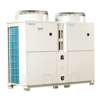
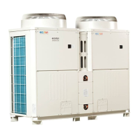
Hot Water Heat Pump Unit CAHV
Installation/Operation Manual
For use with R454C
CAHV-R450YA-HPB(-BS)
Thoroughly read this manual prior to use.
Save this manual for future reference.
Some of the items in this manual may not apply to made-to-order units.
Make sure that this manual is passed on to the end users.
WT09871X01.book 1 ージ 022年7月6日 水曜日 午前11時44分

Other manuals for Mitsubishi Electric CAHV-R450YA-HPB-BS

Questions and Answers:

Mitsubishi Electric CAHV-R450YA-HPB-BS Specifications

General IconGeneral
BrandMitsubishi Electric
ModelCAHV-R450YA-HPB-BS
CategoryHeat Pump
LanguageEnglish

Summary

Safety Precautions

General Safety Warnings

General safety warnings and precautions to ensure safe operation and installation of the unit.

Installation Safety

Installation Warnings

Critical warnings regarding installation procedures to prevent fire, explosion, injury, or unit damage.

Installation and Repair Safety

Electrical Wiring Safety

Cautions for electrical wiring to prevent leakage, breakage, and fire hazards.

1. Installation Site Selection

Installation Conditions

Conditions for selecting an installation site, considering heat sources, noise, wind, and drainage.

Installation Space Requirements

Detailed diagrams and dimensions for ensuring adequate installation space around the unit.

2. Unit Installation

Installation Safety Warnings

Critical warnings about securing the unit and foundation work to prevent toppling and injury.

3. Water Pipe Installation

Piping Diagram and Components

Schematic diagram of the water piping system and a list of its components with their functions.

Notes on Pipe Corrosion

Information on water quality control and standards to prevent pipe corrosion and scaling.

Strainer and Flow Switch Installation

Instructions for installing strainers and flow switches, including maintenance access and specifications.

4. System Configurations

System Configuration Diagrams

Diagrams illustrating how individual and multiple units are connected and configured within a system.

Switch Types and Factory Settings

Overview of switch types on the PCB and their factory default settings for system configuration.

Factory Dip Switch Settings

A table detailing factory settings for dip switches SW4, SW5, and SW6 for various functions.

Configuring Unit Settings

Step-by-step instructions for configuring unit settings using push switches and the LED display.

Settable Items Table

A table listing settable items, their codes, initial values, and ranges, controlled by dip switches.

Individual System Configuration

Procedures for configuring an individual system, including setting dip switches and preset values.

Multiple System Configuration

Procedures for setting up a multiple unit system, including dip switches and rotary switches.

4. Initial Setup Procedures

Signal Input Priority Order

Setting Procedures: Water Temperature

2. Scheduled Operation

3. Preset Temperature Selection

4. Peak-Demand Control

5. Setting Total Units for Multiple System

7. Remote Water Temperature Setting

Setting Water Temperature via Analog Input

Setting Capacity Control Ratio via Analog Input

10. Booster Heater Operation Conditions

5. Electrical Wiring Installation

Main Power Supply and Switch Capacity

Schematic of wiring, wire size, switch capacities, and system impedance requirements.

Electrical Work Warnings

Critical warnings for electrical work, emphasizing qualified personnel and proper grounding.

Electrical Wiring Diagram

Error Codes List

A table listing error codes, their types, causes, and reset methods for troubleshooting.

Error Codes

External Input/Output Signals

6. Troubleshooting

Troubleshooting Without Error Codes

Steps to diagnose and resolve problems that do not generate error codes.

Diagnosing Problems Using Error Codes

Table for diagnosing problems based on error codes, including causes and reset methods.

Diagnosing Problems Using Error Codes

7. Operating the Unit

Initial Operation Procedure

Steps for initial unit operation, including powering up and compressor warm-up.

Using the Remote Controller

Guide on using the remote controller for power ON/OFF and setting operation modes.

Using the Weekly Timer

Instructions for setting a weekly operating schedule via the remote controller.

Using the Period Timer

Instructions for setting specific operating periods and schedules using the remote controller.

Using Power Save Function

Instructions on using the Power Save function to reduce electricity consumption.

Function Setting via Remote Controller

Instructions for setting various functions for connected units via the remote controller's service menu.

Operation Status Monitoring

Steps to check unit running information via the remote controller's operation status monitoring.

Daily Operation Procedures

Instructions for starting and stopping the unit for daily operation.

Using Unit in Sub-freezing or Snowy Conditions

8. Main Specifications

Main Specifications Notes

9. Maintenance

Maintenance and Inspection Guidelines

Guidelines for regular maintenance and inspection of major unit parts.

Maintenance Schedule

Related product manuals