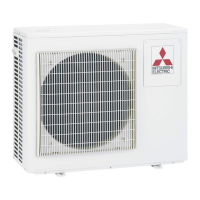
Do you have a question about the Mitsubishi Electric Mr.Slim PUHZ-ZRP35VKA and is the answer not in the manual?
| Brand | Mitsubishi Electric |
|---|---|
| Model | Mr.Slim PUHZ-ZRP35VKA |
| Category | Heat Pump |
| Language | English |
General safety rules and precautions to follow before and during service.
Specific safety warnings and precautions for handling R410A refrigerant.
Lists and specifications of exclusive tools required for R410A refrigerant work.
Explains the function to detect refrigerant leakage and its initial settings.
Describes the system where refrigerant is pre-charged for piping length at shipment.
Details the unit's capability to detect refrigerant leaks over time.
Provides refrigerant charge amounts based on piping length for specific models.
Lists technical specifications for compressor winding resistance at 20°C.
Presents noise level data across different frequencies for various models.
Details standard operational data like capacity, input, and pressures for different model matchings.
Illustrates recommended clearances and service access points around the unit.
Provides information on foundation bolts and directions for piping and wiring connections.
Explains the wiring and connection of the M-NET adapter for communication.
Details power wiring specifications, wire sizes, and circuit ratings for field installation.
Explains connection patterns for separate power supplies for indoor and outdoor units.
Specifies requirements and limitations for indoor-outdoor connecting cables.
Provides guidelines and precautions for M-NET wiring to prevent noise and ensure proper communication.
Provides a summary of error code display and actions to take based on recurring or non-recurring troubles.
Outlines essential checks to perform before and during test runs to ensure proper operation.
Instructions on accessing self-diagnosis, remote controller checks, and error history.
A guide to troubleshoot common operational problems and their causes.
Explains how to set various unit functions using the wired remote controller.
Detailed steps for selecting functions via wired remote controllers.
Steps for configuring unit functions using a wireless remote controller.
Explains function selection using specific wired remote controllers.
Explains how to view operation data and error history using the remote controller.
Detailed guide for monitoring operation data with specific wired remote controllers.
Procedure for monitoring operation data using the PAR-21MAA remote controller.
Describes how to display and use smooth maintenance data for inspection.
Steps to perform smooth maintenance using specific wired remote controllers.
Guide for performing smooth maintenance using the PAR-21MAA remote controller.
Instructions for performing refrigerant leak checks and initial learning.
Steps to perform refrigerant leak checks with specific wired remote controllers.
Guide for performing refrigerant leak checks using the PAR-21MAA remote controller.
Step-by-step guide to remove external panels and grilles from the outdoor unit.
Instructions for safely removing the fan motor assembly from the unit.
Procedure for accessing and removing the electrical parts box.
Guide for removing various outdoor thermistors, noting combined replacements.
Instructions for removing the 4-way valve coil and LEV coils.
Detailed steps for removing the 4-way valve assembly from the unit.
Procedure for removing the Linear Expansion Valve (LEV) coil.
Steps for safely removing the high pressure switch.
Guide for removing the reactor (ACL) component.
Detailed procedure for safely removing the compressor unit.
Instructions for removing the power receiver component.


 Loading...