12
GBDFEINLPGRRUTRCZSVSLHGPO
s Consult all related regulations and power companies beforehand.
Warning:
Electrical work should be handled by qualified electrical engineers in ac-
cordance with all related regulations and attached instruction manuals. Spe-
cial circuits should also be used. If there is a lack of power capacity or a
deficiency in electrical work, it may cause a risk of electric shock or fire.
s Connect all wires securely.
• Fix power source wiring to control box by using buffer bushing for tensile force
(PG connection or the like).
[Fig. 5.0.1] (P.6)
A Control box B Power source wiring
C ø21 hole (closed rubber bushing) D Transmission wiring
s Never connect the power cable to the terminal board for control cables.
(Otherwise it may be broken.)
s Be sure to wire between the control wire terminal boards for indoor unit,
outdoor unit and BC controller.
Use non-polarized 2-wire as transmission cables.
Use 2-core shielding cables (CVVS, CPEVS) of more than 1.25 mm
2
in diameter
as transmission cables.
4.3. Insulating refrigerant pipes
Be sure to add insulation work to refrigerant piping by covering high-pressure pipe and
low-pressure pipe separately with enough thickness heat-resistant polyethylene, so
that no gap is observed in the joint between indoor unit and insulating material, and
insulating materials themselves. When insulation work is insufficient, there is a possibility
of condensation drip, etc. Pay special attention to insulation work in the ceiling plenum.
[Fig. 4.3.1] (P.6)
A Locally procured insulating material for pipes
B Bind here using band or tape. C Do not leave any opening.
D Lap margin: more than 40 E Insulating material (field supply)
F Unit side insulating material
• Insulation materials for the pipes to be added on site must meet the following
specifications:
Outdoor unit High-pressure pipe 10 mm or more
-BC controller Low-pressure pipe 20 mm or more
BC controller Pipe size 6.35 mm to 25.4 mm 10 mm or more
-indoor unit Pipe size 28.58 mm to 38.1 mm 15 mm or more
Temperature Resistance 100°C min.
• Installation of pipes in a high-temperature high-humidity environment, such as
the top floor of a building, may require the use of insulation materials thicker
than the ones specified in the chart above.
• When certain specifications presented by the client must be met, ensure that
they also meet the specifications on the chart above.
• The brazed connections must be covered with the insulations, its cutting surface
upward and fastened with the bands.
4.4. Drain piping work
1. Drain piping work
• Ensure that the drain piping is downward (pitch of more than 1/100) to the
outdoor (discharge) side. If it is impossible to take any downward pitch, use an
optionally available drain-up mechanism to obtain a downward pitch of more
than 1/100.
• Ensure that any cross-wise drain piping is less than 20 m. If the drain piping is
long, support it with metal brackets to prevent it from bending, warping, or
vibrating.
Molded case
circuit breaker
Earth leakage
breaker
• Connect the supplied drain hose to the discharge port on the unit body. Use
hard vinyl chloride pipes VP-25 (ø32) for drain piping (2). Tighten the supplied
drain hose onto the discharge port using the supplied hose band. (For this, do
not use any adhesive because the drain hose will need to be removed for
servicing at a later date.)
• Do not use any odor trap around the discharge port.
[Fig. 4.4.1] (P.6)
A: 25 cm B: 1.5 – 2 m
A Downward pitch of more than 1/100
B Insulating material C Supporting bracket
D Drain discharge port E Drain hose (200 mm long, accessory)
F Tie band (accessory) G Hose band (accessory)
•
As shown in 3, install a collecting pipe about 10 cm below the drain ports and give
it a downward pitch of more than 1/100. This collecting pipe should be of VP-30.
• Set the end of drain piping in a place without any risk of odor generation.
•
Do not put the end of drain piping into any drain where ionic gases are generated.
• Drain piping may be installed in any direction. However, please be sure to
observe the above instructions.
• When using an optionally available drain-up mechanism, follow its instruction
manual regarding its installation and use.
[Fig. 4.4.2] (P.6)
A BC controller B Indoor unit
C Collecting pipe D Please ensure this length is at least 10 cm.
2. Discharge test
After completing drain piping work, open the BC controller panel, and test drain
discharge using a small amount of water. Also, check to see that there is no water
leakage from the connections.
3. Insulating drain pipes
Provide sufficient insulation to the drain pipes just as for refrigerant pipes.
Caution:
Be sure to provide drain piping with heat inslation in order to prevent excess
condensation. Without drain piping, water may leak from the unit causing
damage to your property.
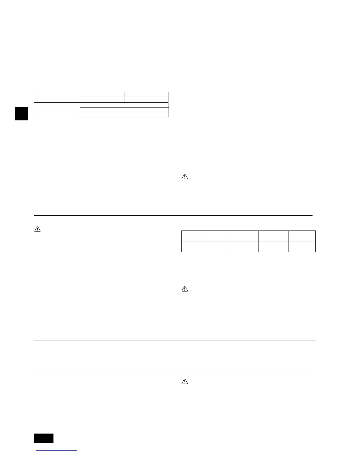
The switch capacity of the main power to BC controllers and the wire size are as
follows:
Switch (A)
Wire size
Capacity Fuse
16 16 20 A 20 A 30 mA 1.5 mm
2
0.1 s or less
• For other detailed information, refer to the outdoor unit installation manual.
• Power supply cords of appliances shall not be lighter than design 245 IEC 53
or 227 IEC 53.
• A switch with at least 3 mm contact separation in each pole shall be provided
by the Air conditioner installation.
Caution:
Do not use anything other than the correct capacity fuse and breaker. Using
fuse, conductor or copper wire with too large capacity may cause a risk of
malfunction or fire.
Ensure that the outdoor units are put to the ground. Do not connect the earth
cable to any gas pipe, water pipe, lightening rod or telephone earth cable.
Incomplete grounding may cause a risk of electric shock.
6. Setting addresses and operating units
7. Test run
Before commencing a test run please check the fol-
lowing:
s After installing, piping and wiring the indoor units and BC controllers,
check to see again that there is no refrigerant leakage and no slack on
power and control cables.
s Use a 500 V megger to check that there is an insulation resistance of
more than 1.0 MΩ between the power terminal block and the ground. If it
is less than 1.0 MΩ, do not operate the unit.
5. Electrical work
The address switch of each BC controller is set to “000” when shipped from the
factory.
• Set the address switch to 1 + the address of the outdoor unit.
s The BC controller address should generally be set to 1 + the address of
the outdoor unit. However, if this would result in it having the same ad-
dress as another outdoor unit, set the address between 51 and 100, mak-
ing sure that it is different from the address of other controllers.
• Please refer to the outdoor unit installation manual.
Caution:
Never measure the insulation resistance of the terminal block for any control
cables.
WT05845X01_en.p65 10.1.29, 0:03 PM12
 Loading...