EasyManua.ls Logo

Mitsubishi Electric CITY MULTI PEFY-AF1200CFM-E User Manual

Mitsubishi Electric CITY MULTI PEFY-AF1200CFM-E
40 pages
To Next Page IconTo Next Page
Page #1 background imageLoading...
Page #1 background image

Questions and Answers:

Mitsubishi Electric CITY MULTI PEFY-AF1200CFM-E Specifications

General IconGeneral
SeriesCITY MULTI
External Static Pressure50 Pa
RefrigerantR410A
TypeCeiling Concealed
Power Input (Heating)0.345 kW
Sound Pressure Level (Heating)48 dB(A)
Power Supply220-240V, 50Hz
Indoor Unit TypeCeiling Concealed
Operating Temperature (Cooling)19 to 46 °C
Operating Temperature (Heating)-15 to 24 °C

Summary

Safety Precautions

Symbol Explanations

Explains warning and caution symbols used in the manual.

Installation and Electrical Work Safety

Covers safe installation practices and electrical work precautions.

Warning Labels and Modifications

Emphasizes reading unit labels and avoiding unauthorized modifications.

Refrigerant Leak and Safety Measures

Details actions for refrigerant leaks and general safety during operation.

Handling Precautions for R410A Refrigerant

Specific guidance on using and handling R410A refrigerant safely.

Unit Features

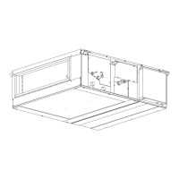
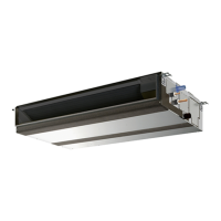
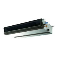
PEFY-AF1200CFM-E Model Features

Describes the main features and components of the PEFY-AF1200CFM-E model.

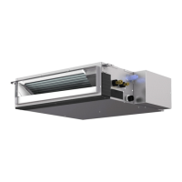
PEFY-AF1200CFMR-E Model Features

Describes the main features and components of the PEFY-AF1200CFMR-E model.

Components and Functions

Indoor Unit Components Description

Details the components of the indoor unit.

Remote Controller Overview and Buttons

Introduces the simple remote controller and its buttons.

Remote Controller Display Icons Explained

Explains various icons shown on the remote controller display.

Technical Specifications

PEFY-AF1200CFM-E Specifications

Lists detailed technical data and capacities for the PEFY-AF1200CFM-E model.

PEFY-AF1200CFMR-E Specifications

Lists detailed technical data and capacities for the PEFY-AF1200CFMR-E model.

Electrical Component Specifications

Details specifications for electrical components used in the units.

Outlines and Dimensions

PEFY-AF1200CFM-E Unit Dimensions and Drawings

Provides dimensional drawings and measurements for the PEFY-AF1200CFM-E unit.

PEFY-AF1200CFMR-E Unit Dimensions and Drawings

Provides dimensional drawings and measurements for the PEFY-AF1200CFMR-E unit.

Wiring Diagram

PEFY-AF1200CFM-E Wiring Schematic

Illustrates the internal wiring connections for the PEFY-AF1200CFM-E unit.

PEFY-AF1200CFMR-E Wiring Schematic

Illustrates the internal wiring connections for the PEFY-AF1200CFMR-E unit.

Refrigerant System Diagram

PEFY-AF1200CFM-E Refrigerant Circuit Diagram

Shows the flow of refrigerant through the PEFY-AF1200CFM-E system.

PEFY-AF1200CFMR-E Refrigerant Circuit Diagram

Shows the flow of refrigerant through the PEFY-AF1200CFMR-E system.

Microprocessor Control

Auto Operation Mode and Thermoregulation

Explains the auto operation mode and thermoregulation control for PEFY-AF1200CFM-E.

PEFY-AF1200CFMR-E Thermoregulation and Mode Change

Details PEFY-AF1200CFMR-E thermoregulation, including mode change logic.

Troubleshooting

Error Code 2502: Drain Pump Fault Details

Details error 2502, its cause, detection, and remedies for drain pump issues.

Error Code 4109: Fan Fault Troubleshooting

Covers error 4109, its definition, and troubleshooting steps for fan faults.

Sensor Fault Error Codes 5101-5104

Addresses sensor faults (outlet air, pipe, gas-side, intake air) and their troubleshooting.

Error Code 5401: Humidity Sensor Fault

Details error 5401, including sensor failure and control board issues.

Error Code 5701: Float Switch Connector Fault

Explains error 5701 related to loose float switch connectors.

Troubleshooting Check Methods: Thermistors and Sensors

Describes how to check thermistors and humidity sensors for faults.

Troubleshooting Check Methods: Fan Motor Resistance

Explains how to test the fan motor for resistance issues.

Troubleshooting Check Methods: Linear Expansion Valve (LEV) Resistance

Details resistance checks for the LEV and its operation summary.

Linear Expansion Valve (LEV) Operation and Fault Diagnosis

Explains LEV operation, pulse signals, and troubleshooting for locked or failed LEVs.

LEV Leaks, Misconnections, and Float Switch Checks

Covers LEV leaks, misconnections, drain-up mechanism, and float switch checks.

Address Switch Setting Procedure for Indoor Units

Guides on setting unit addresses using rotary switches SW11 and SW12.

Control Board Voltage Test Points and Dipswitch SW1/SW3

Identifies control board test points and SW1/SW3 dipswitch settings.

Dipswitch SW3 Settings for Target Temperature

Details dipswitch settings for target temperature and dew point temperature adjustment.

Dipswitch Settings for Capacity (SW2) and Model (SW4/SW5/SW8/SWC)

Covers dipswitch settings for capacity code (SW2) and model selection (SW4, SW5, SW8, SWC).

Disassembly Procedure

Overview of Component Locations

Identifies the positions of major internal components within the unit.

Service Panel Removal Instructions

Provides instructions on how to remove service panels A and B.

Control Box Cover Removal and Access

Details removing the control box cover for access to switches and wiring.

Control Box Internal Layout and Wiring Diagrams

Shows internal control box layouts and lists wiring connections for disassembly.

Humidity Sensor, LEV, and Pipe Thermistor Removal

Guides on removing humidity sensors, LEVs, and pipe thermistors.

Drainpan Removal Procedure

Provides steps for safely removing the drainpan from the unit.

Pump, Float Switch, and Air Temp Thermistor Removal

Details the process for removing the pump, float switch, and supply air temperature thermistor.

Fan and Fan Motor Removal Procedure

Outlines the steps for disassembling and removing the fan and fan motor.

Heat Exchanger Removal Procedure

Provides instructions for removing the main and reheat coils of the heat exchanger.

Related product manuals