Do you have a question about the Mitsubishi Electric CITY MULTI PEFY-P06NMAU-E and is the answer not in the manual?
| Brand | Mitsubishi Electric |
|---|---|
| Model | CITY MULTI PEFY-P06NMAU-E |
| Category | Air Conditioner |
| Language | English |
Explains symbols used for warnings and cautions in the manual.
Details precautions for handling R410A refrigerant, including piping and tools.
Lists models and their cooling/heating capacities in BTU/h and kW.
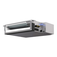
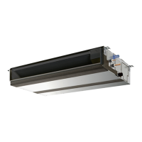
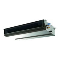
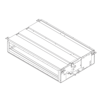
Describes the indoor unit, including inlet and outlet air flow.
Details the PAR-21MAA remote controller and its buttons.
Explains the various indicators and symbols shown on the remote controller display.
Provides detailed specifications like power, capacity, dimensions, and components for specific models.
Details specifications for PEFY-P18, P24, P27, and P30 NMAU-E models.
Provides specifications for PEFY-P36, P48, and P54 NMAU-E models.
Lists electrical components and their specifications for various models.
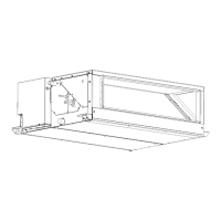
Illustrates unit dimensions, required space for maintenance, and clearances.
Depicts the internal wiring schematic of the indoor control board and connections.
Defines symbols used in the wiring diagram for clarity and understanding.
Illustrates the refrigerant flow and specifies pipe diameters for different models.
Explains how to operate the unit in cool mode, including thermoregulation and anti-freezing control.
Details the operation of the unit in dry mode, covering thermoregulation and fan control.
Describes how the fan operates independently of other modes, including speed settings and drain pump control.
Explains heat operation, including thermoregulation, fan control, and hot adjust mode.
Details the automatic cool/heat changeover operation, including mode change conditions.
Explains drain pump and float switch operation when the unit is stopped.
Outlines heater control based on outdoor conditions and DIP S/W settings.
Details heater output patterns and fan control settings for different unit types.
Describes the installation of the PAC-YU25HT for driving an electric heater with the air conditioner.
Provides wiring diagrams and restrictions for the external heater adapter installation.
Details methods for checking components like thermistors, fan motors, and linear expansion valves.
Explains the operation of the LEV and its connection to the indoor control board.
Describes LEV operation, common faults, and remedies for locked or shorted LEV.
Covers troubleshooting for LEV leaks, connector issues, drain mechanism, and float switch.
Provides a troubleshooting guide for the indoor unit's DC fan motor when it fails to run.
Explains how to set addresses using rotary switches on the indoor unit control board.
Identifies key voltage test points on the indoor control board for diagnostics.
Details factory default dipswitch settings for functions like thermistor, filter, and intake air.
Explains dipswitch settings for capacity code and model selection.
Describes how to set the power voltage using dipswitches on the indoor unit.
Covers address setting for network remotes and connection number settings.
Provides steps for removing the control box cover and accessing the control box.
Details the procedure for removing the intake air thermistor holder and thermistor.
Explains how to remove the filter, bottom plate, and drainpan from the unit.
Describes the process for removing heat exchanger covers and thermistors for gas and liquid pipes.
Details the steps for removing the fan casing, motor cable, fan motor, and Sirocco fan.
Provides instructions for removing the heat exchanger cover and the heat exchanger itself.