EasyManua.ls Logo

Mitsubishi Electric City Multi PEFY-P250VMH-E User Manual

Mitsubishi Electric City Multi PEFY-P250VMH-E
31 pages
To Next Page IconTo Next Page
Page #1 background imageLoading...
Page #1 background image
TECHNICAL & SERVICE MANUAL
Air-Conditioners For Building Application
<Indoor unit>
2004
Models
Ceiling Concealed
Series PEFY
PEFY-P40VMH-E,PEFY-P50VMH-E
PEFY-P63VMH-E,PEFY-P71VMH-E
PEFY-P80VMH-E,PEFY-P100VMH-E
PEFY-P125VMH-E,PEFY-P140VMH-E
PEFY-P200VMH-E,PEFY-P250VMH-E
INDOOR UNIT
CONTENTS
SAFETY PRECAUTIONS ·························1
1. FEATURES ···········································3
2. PART NAMES AND FUNCTIONS ········4
3. SPECIFICATION ···································6
4. OUTLINES AND DIMENSIONS············9
5. WIRING DIAGRAM ·····························11
6.
REFRIGERANT SYSTEM DIAGRAM
13····
7. TROUBLE SHOOTING·······················14
8. DISASSEMBLY PROCEDURE···········
17
For use with the R410A & R407C & R22
Question and Answer IconNeed help?

Do you have a question about the Mitsubishi Electric City Multi PEFY-P250VMH-E and is the answer not in the manual?

Mitsubishi Electric City Multi PEFY-P250VMH-E Specifications

General IconGeneral
SeriesCity Multi
Cooling Capacity25.0 kW
Heating Capacity28.0 kW
RefrigerantR410A
Heating Capacity (kW)28.0
Cooling Capacity (kW)25.0
SEER6.50
Power Supply380-415V, 50Hz
Operating Temperature (Cooling)0 to 46 °C
Operating Temperature (Heating)-15 to 24 °C

Summary

SAFETY PRECAUTIONS

Installation and Electrical Safety

Key safety measures before installation and electrical work.

Refrigerant Handling Precautions

Specific safety guidelines for R410A and R407C refrigerants.

FEATURES

Model Capacities and Specifications

Lists models and their cooling/heating capacities.

PART NAMES AND FUNCTIONS

Indoor Unit Component Identification

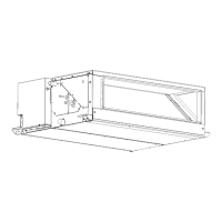
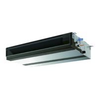
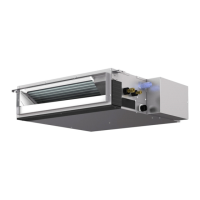
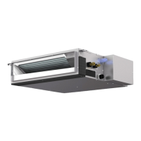
Identifies and describes parts of the indoor unit.

Remote Controller Operation and Display

Explains the remote controller's buttons and display functions.

SPECIFICATION

Technical Performance Specifications

Details cooling/heating capacity, power, dimensions, and noise levels.

Electrical Component Details

Lists specifications for electrical parts like transformers and motors.

OUTLINES AND DIMENSIONS

Unit Dimensions and Clearances

Provides detailed physical measurements and required space for installation.

WIRING DIAGRAM

Electrical Wiring Schematics

Illustrates the electrical connections for various models.

Wiring Diagram Symbol Key

Explains the meaning of symbols used in the wiring diagrams.

REFRIGERANT SYSTEM DIAGRAM

Refrigerant Pipe Size Chart

Specifies refrigerant pipe diameters for different models and refrigerants.

TROUBLE SHOOTING

Component Testing Procedures

Guides on how to check the functionality of key components.

Address and DIP Switch Configuration

Instructions for setting unit addresses and dip switches.

Test Run and Indicator Functions

Procedures for performing a test run and understanding LED indicators.

DISASSEMBLY PROCEDURE

Control Box Component Removal

Detailed steps for removing and accessing the control box.

Fan Motor Assembly Disassembly

Guide to removing the fan motor and related parts.

LEV and Thermistor Sensor Removal

Steps for disassembling LEV and thermistor sensors.

Heat Exchanger Unit Removal

Procedure for removing the main heat exchanger.

Internal Control Box Layout

Diagram showing the arrangement of components within the control box.

Sensor Position Guide

Illustrates the placement of various sensors on different models.

Related product manuals