Do you have a question about the Mitsubishi Electric CITY MULTI PEFY Series and is the answer not in the manual?
| Brand | Mitsubishi Electric |
|---|---|
| Model | CITY MULTI PEFY Series |
| Category | Air Conditioner |
| Language | English |
Covers installation, electrical work, and general warnings.
Explains warning and caution symbols used in the manual.
Specific safety measures for units using R410A refrigerant.
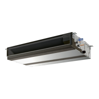
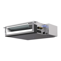
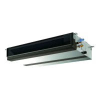
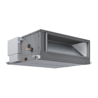
Introduces the PEFY Series Ceiling Concealed units.
Identifies key parts of the indoor unit.
Describes the remote controller and its buttons.
Explains the icons and modes shown on the remote display.
Details cooling/heating capacities, temperature ranges, and power inputs.
Lists specifications for electrical parts like thermistors and motors.
Provides physical dimensions for PEFY-P36 and PEFY-P48 models.
Specifies required space for servicing the unit, including access doors.
Provides physical dimensions for PEFY-P72 and PEFY-P96 models.
Specifies required space for servicing larger unit models.
Illustrates the electrical connections for PEFY-P36 and PEFY-P48 models.
Illustrates the electrical connections for PEFY-P72 and PEFY-P96 models.
Shows the refrigerant circuit and pipe sizes for different models.
Outlines checks for thermistors, fan motors, and LEVs.
Explains how the Linear Expansion Valve (LEV) functions.
Provides troubleshooting steps for LEV issues and potential solutions.
Covers checks for drain pump and float switch malfunctions.
Addresses problems with the indoor unit fan not running.
Details how to set unit addresses using rotary switches.
Identifies key test points on the control board for voltage checks.
Explains the function and settings of various dip-switches for configuration.
Describes how to adjust fan speed for different static pressures.
Details the function to mitigate cold air discharge during heating.
Specific guidance on setting unit addresses using rotary switches.
Explains the meaning of LED indicators on the service board.
Step-by-step guide for disassembling the control box on PEFY-P36/48.
Steps for removing the fan and motor assembly on PEFY-P36/48.
Steps for removing LEV and thermistor components on PEFY-P36/48.
Steps for disassembling the drain pump on PEFY-P36/48.
Steps for removing the heat exchanger on PEFY-P36/48.
Continued steps for heat exchanger removal on PEFY-P36/48.
Diagram showing internal components of the control box for PEFY-P36/48.
Shows the positions of thermistors on the PEFY-P36/48 unit.
Step-by-step guide for disassembling the control box on PEFY-P72/96.
Steps for removing the fan and motor assembly on PEFY-P72/96.
Continued steps for fan/motor removal on PEFY-P72/96.
Steps for removing LEV and thermistors on PEFY-P72/96.
Steps for disassembling the drain pump on PEFY-P72/96.
Continued steps for drain pump removal on PEFY-P72/96.
Steps for removing the heat exchanger on PEFY-P72/96.
Continued steps for heat exchanger removal on PEFY-P72/96.
Diagram showing internal components of the control box for PEFY-P72/96.
Shows the positions of thermistors on the PEFY-P72/96 unit.