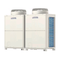
Do you have a question about the Mitsubishi Electric CITY MULTI PUHY-P400YEM-A and is the answer not in the manual?
| Series | CITY MULTI |
|---|---|
| Cooling Capacity (kW) | 40.0 |
| Heating Capacity (kW) | 45.0 |
| Refrigerant | R410A |
| Type | VRF System |
| Power Supply | 380-415V, 50Hz |
| Dimensions (Indoor Unit) | N/A (This model is an outdoor unit) |
| Weight (Indoor Unit) | N/A (This model is an outdoor unit) |
| Operating Temperature (Cooling) | -5 to +46°C |
| Operating Temperature (Heating) | -15°C to 15.5°C |
Essential safety guidelines to follow before starting installation or electrical work on the unit.
Explanation of warning symbols and cautionary marks used throughout the manual.
Detailed procedures for storage, machining, brazing, testing, vacuuming, charging, and dryer replacement.
Visual identification of key internal components in the variable and constant capacity units.
Diagrams illustrating refrigerant flow and thermal sensor locations for various models.
Wiring diagrams for PUHY-(P)400/500YEM(K,C)-A and PUHN-(P)200/250YEM(K,C)-A units.
Configuration settings for outdoor unit DIP switches, including address setting and operation modes.
DIP SW configurations for indoor units, covering filter detection, vane control, and model selection.
Specific DIP SW4 settings for phase control, circuit board usage, and airflow options.
Explanation of switch functions on the remote controller for registering indoor units and system attributes.
Description of unit attributes displayed on the remote controller during group registration.
Step-by-step guide for registering indoor units to the remote controller and assigning addresses.
Procedure for retrieving and confirming group registration information and unit attributes.
Steps for deleting group registration information of indoor units from the remote controller.
Procedure for deleting information related to non-existent addresses or errors.
Explanation of outdoor unit control strategies, including initial processing and compressor operations.
Flowcharts illustrating the operational logic for outdoor and indoor units in cooling, heating, and dry modes.
Detailed functions of major components like sensors, compressors, and valves in the system.
Graphs showing the resistance-temperature characteristics of various thermistors used in the unit.
Procedure for adjusting refrigerant volume using the control board switches and LED monitor.
Operating characteristics, symptoms of incorrect refrigerant amounts, and adjustment procedures.
Checks for pressure sensors and sensor configurations to identify potential faults.
Table of error codes and corresponding causes, checking methods, and countermeasures.
Explanation of how to read and interpret the service LEDs on the control circuit board for diagnostics.
Steps for locating leaks in extension piping or indoor units during cooling mode, including pump down.
Procedure for locating leaks in the outdoor unit during cooling mode, involving test runs and data checks.
Steps for locating leaks in extension piping or indoor units during heating mode, including test runs.
Procedure for locating leaks in the outdoor unit during heating mode, including refrigerant removal and vacuum creation.
Explanations and notes regarding refrigerant composition checks, including stabilization and calibration.


 Loading...