EasyManua.ls Logo

Mitsubishi Electric City Multi PUMY-P250YBM User Manual

Mitsubishi Electric City Multi PUMY-P250YBM
34 pages
To Next Page IconTo Next Page
Page #1 background imageLoading...
Page #1 background image
For use with R410A
Air-Conditioners
PUMY-P250YBM
PUMY-P300YBM
FOR INSTALLER
INSTALLATION MANUAL
MONTAJ ELKİTABI
INSTALLATIONSMANUAL
INSTALLATIONSMANUAL
MANUAL DE INSTALAÇÃO
ΕΓΧΕΙΡΙΔΙΟ ΟΔΗΓΙΩΝ ΕΓΚΑΤΑΣΤΑΣΗΣ
MANUALE DI INSTALLAZIONE
MANUAL DE INSTALACIÓN
INSTALLATIEHANDLEIDING
MANUEL D’INSTALLATION
INSTALLATIONSHANDBUCH
РЪКОВОДСТВО ЗА МОНТАЖ
INSTRUKCJA MONTAŻU
INSTALLASJONSHÅNDBOK
ASENNUSOPAS
INSTALAČNÍ PŘÍRUČKA
NÁVOD NA INŠTALÁCIU
TELEPÍTÉSI KÉZIKÖNYV
NAMESTITVENI PRIROČNIK
MANUAL DE INSTALARE
PAIGALDUSJUHEND
MONTĀŽAS ROKASGRĀMATA
MONTAVIMO VADOVAS
PRIRUČNIK ZA POSTAVLJANJE
UPUTSTVO ZA UGRADNJU
English
Deutsch
Français
Nederlands
Español
Italiano
Ελληνικά
Português
Dansk
Svenska
Türkçe
Български
Polski
Norsk
Suomi
Čeština
Slovenčina
Magyar
Slovenščina
Română
Eesti
Latviski
Lietuviškai
Hrvatski
Srpski
PER L’INSTALLATORE
VOOR DE INSTALLATEUR
PARA EL INSTALADOR
FÜR INSTALLATEURE
POUR L’INSTALLATEUR
FÖR INSTALLATÖREN
TIL INSTALLATØREN
PARA O INSTALADOR
ΓΙΑ ΑΥΤΟΝ ΠΟΥ ΚΑΝΕΙ ΤΗΝ ΕΓΚΑΤΑΣΤΑΣΗ
MONTÖR İÇİN
ЗА МОНТАЖНИКА
DLA INSTALATORA
FOR MONTØR
ASENTAJALLE
PRO MONTÁŽNÍ PRACOVNÍKY
PRE MONTÉRA
A TELEPÍTŐ RÉSZÉRE
ZA MONTERJA
PENTRU INSTALATOR
PAIGALDAJALE
UZSTĀDĪŠANAS SPECIĀLISTAM
SKIRTA MONTUOTOJUI
ZA INSTALATERA
ZA MONTERA
РУКОВОДСТВО ПО УСТАНОВКЕ
ПОСІБНИК З УСТАНОВЛЕННЯ
Русский
Українська
ДЛЯ УСТАНОВИТЕЛЯ
ДЛЯ СПЕЦІАЛІСТА З МОНТАЖУ
BT79A020W01_cover1.indd 1 2020/09/25 17:16:13
Question and Answer IconNeed help?

Do you have a question about the Mitsubishi Electric City Multi PUMY-P250YBM and is the answer not in the manual?

Mitsubishi Electric City Multi PUMY-P250YBM Specifications

General IconGeneral
SeriesCity Multi
TypeHeat Pump
Cooling Capacity25.0 kW
Heating Capacity28.0 kW
RefrigerantR410A
Operating Temperature Range (Cooling)-5°C to 46°C
Power Supply380-415V, 50Hz, 3-Phase

Summary

Safety Precautions

Confirmation of Parts Attached

Confirms the parts supplied with the outdoor unit for grounding the S terminal.

Before Installation

Precautions to take before starting the installation process.

Before Installation (Relocation)

Precautions for safely handling and moving the unit.

Before Electric Work

Precautions related to electrical wiring and connections.

Before Starting the Test Run

Steps to take before performing the initial operational test.

Using R410A Refrigerant Air Conditioners

Specific precautions for using R410A refrigerant systems.

Accessories of Outdoor Unit

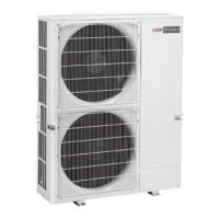
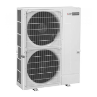
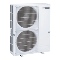
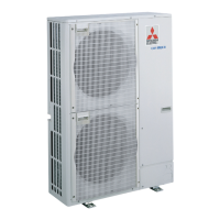
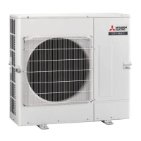
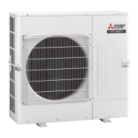
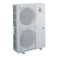
Lists and illustrates accessories included with the outdoor unit.

Installation Location

Choosing the Outdoor Unit Installation Location

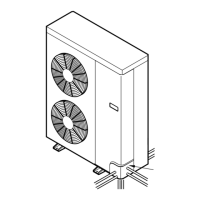
Guidelines for selecting an appropriate installation site for the outdoor unit.

Constraints on Indoor Unit Installation

Details on compatible indoor units and connection quantity limits.

Connecting a PEFY-P-VMA3-E

Specifies valid combinations for connecting PEFY-P-VMA3-E indoor units.

Connecting a PLFY-EP-VEM-E

Lists authorized connectable indoor units for PLFY-EP-VEM-E.

Ventilation and Service Space

Required clearances for ventilation and service access.

When Installing a Single Outdoor Unit

Minimum dimensions for single outdoor unit installation.

When Installing Multiple Outdoor Units

Clearance requirements for installing multiple outdoor units.

Windy Location Installation

Precautions for installing units in locations exposed to strong winds.

Installing the Outdoor Unit

Installing the Refrigerant Piping

Precautions for Devices That Use R410A Refrigerant

Key precautions when working with R410A refrigerant systems.

Connection Without Branch box

Details on piping connections without using a branch box.

Connection With Branch box

Details on piping connections using a branch box.

Mixing System (Connection with Branch box)

Piping for mixed systems of City Multi and M series with branch boxes.

4.1.3-1 In Case of Using 1-Branch box

Piping specifications for a 1-branch box in a mixed system.

4.1.3-2 In Case of Using 2-Branch boxes

Piping specifications for 2-branch boxes in a mixed system.

4.1.3-3 In Case of Using 3-Branch boxes

Piping specifications for 3-branch boxes in a mixed system.

4.1.3-4 Selecting Pipe Size

Guide for selecting pipe sizes in various connection configurations.

Connecting Pipes

Instructions and methods for connecting refrigerant pipes.

Additional Refrigerant Charge

Procedure to calculate and charge additional refrigerant.

Refrigerant Piping

Detailed steps for refrigerant piping installation and cover attachment.

Installing the Refrigerant Piping (Main Pipe)

Procedure for installing the main refrigerant piping.

4.5.1. Removing Pinch Connection Pipes

Procedure to remove pinch connection pipes before piping connection.

4.5.2. Piping Connection and Valve Operation

Steps for connecting pipes and operating valves.

Refrigerant Pipe Airtight Testing Method

Method for testing the airtightness of refrigerant pipes.

Drainage Piping Work

Outdoor Unit Drainage Pipe Connection

Instructions for connecting the outdoor unit drainage pipe.

Electrical Work

Caution

General safety precautions and warnings for electrical work.

Control Box and Connecting Position of Wiring

Details on control box connections and wiring locations.

Wiring of Main Power Supply and Equipment Capacity

Wiring diagrams and specifications for power supply and capacity.

Wiring Transmission Cables

Details on types of transmission and remote control cables.

1. Wiring Transmission Cables

Specifications for wiring transmission cables.

2. M-NET Remote Control Cables

Specifications for M-NET remote control cables.

3. MA Remote Control Cable

Specifications for MA remote control cables.

Example of a Group Operation System with Multiple Outdoor Units

Wiring and address settings for group operation systems.

Example of Transmission Cable Wiring: Connecting with Branch box

Example wiring diagram for connecting with a branch box.

Example of Transmission Cable Wiring: Mixing System

Example wiring diagram for mixing systems.

Address Setting

Guide for setting unit addresses using DIP switches.

Test Run

Before Test Run

Checks to perform before starting the test run.

Test Run

Procedures for performing the test run.

7.2.1. Using Remote Controller

Procedure for conducting a test run using the remote controller.

7.2.2. Using SW3 in Outdoor Unit

Procedure for conducting a test run using the outdoor unit's SW3 switch.

Refrigerant Collecting (Pump Down)

Special Functions

OUTDOOR UNIT INPUT/OUTPUT CONNECTOR

Details on outdoor unit connectors and their functions.

State (CN51)

Description of the state of the outdoor unit connector CN51.

Auto Change Over (CN3N)

Functionality for auto change over via CN3N connector.

Silent Mode / Demand Control (CN3D)

Settings for silent mode and demand control via CN3D connector.

External Static Pressure Mode (30 Pa)

Enabling the external static pressure mode via DIP switch.

Related product manuals