EasyManua.ls Logo

Mitsubishi Electric CITY MULTI PURY-P126 User Manual

Mitsubishi Electric CITY MULTI PURY-P126
404 pages
To Next Page IconTo Next Page
Page #1 background imageLoading...
Page #1 background image
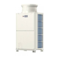
Models PUHY-P72, P96, P108, P126, P144TGMU-A
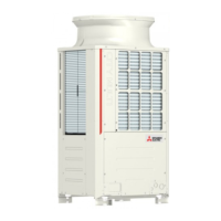
PUHY-P168, P192, P204, P216, P234TGMU-A
PURY-P72, P96, P108, P126, P144TGMU-A
PURY-P168, P192, P204, P216, P234TGMU-A
Service Handbook
AIR CONDITIONERS CITY MULTI
HEAD OFFICE: MITSUBISHI DENKI BLDG., 2-2-3, MARUNOUCHI, CHIYODA-KU, TOKYO 100-8310, JAPAN
Service Handbook PUHY-P72, P96, P108, P126, P144TGMU-A
PUHY-P168, P192, P204, P216, P234TGMU-A
PURY-P72, P96, P108, P126, P144TGMU-A
PURY-P168, P192, P204, P216, P234TGMU-A
Issued in Oct. 2005 HWE05020
New publication effective Oct. 2005.
Specifications subject to change without notice.
Service Handbook
PURY-P72, P96, P108, P126, P144,P168, P192, P204, P216, P234TGMU-A
PUHY-P72, P96, P108, P126, P144,P168, P192, P204, P216, P234TGMU-A

Table of Contents

Question and Answer IconNeed help?

Do you have a question about the Mitsubishi Electric CITY MULTI PURY-P126 and is the answer not in the manual?

Mitsubishi Electric CITY MULTI PURY-P126 Specifications

General IconGeneral
BrandMitsubishi Electric
ModelCITY MULTI PURY-P126
CategoryAir Conditioner
LanguageEnglish

Summary

Safety Precautions

Before installing the unit (moving and reinstalling the unit) and performing electrical work

WARNING

Electrical safety and installation warnings.

V Electrical Wiring Diagram

[1] Electrical Wiring Diagram of the Outdoor Unit

Electrical wiring diagram for PUHY-P72 to P144 models.

VI Refrigerant Circuit

[1] Refrigerant Circuit Figure

Refrigerant circuit diagrams for various outdoor unit models.

[2] Principal Parts and Functions

Description of major components in the refrigerant circuit.

VII Control

[1] Functions and Factory Settings of the Dipswitches

Functions and factory settings for outdoor unit dipswitches.

VIII Test Run Mode

[1] Items to be checked before a Test Run

Pre-test run checks for refrigerant leaks and electrical connections.

[2] Test Run Method

Procedure for performing a test run using the MA deluxe remote controller.

[5] Refrigerant Amount Adjust Mode

Procedures for adjusting refrigerant amount in PUHY systems.

IX Troubleshooting

[1] Check Code Lists

List of error codes, their definitions, and corresponding units.

[2] Responding to Error Display on the Remote Controller

Troubleshooting steps for errors displayed on the remote controller.

[4] Troubleshooting Principal Parts

Diagnostic procedures for key components like sensors and valves.

X LED monitor display on the outdoor unit board

Related product manuals