EasyManua.ls Logo

Mitsubishi Electric DD-4030 User Manual

Mitsubishi Electric DD-4030
40 pages
To Next Page IconTo Next Page
Page #1 background imageLoading...
Page #1 background image
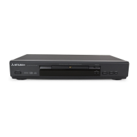
DVD PLAYER
2002
MODEL
DD-4030
Manual
Service
MITSUBISHI ELECTRIC
TABLE OF CONTENTS
SPECIFICATIONS . . . . . . . . . . . . . . . . . . . . . . . . . . . . . . . . . . . . . . . . . . . . . . . . . . . . . . . . . . . . . . . . . . . . . . .1-1-1
LASER BEAM SAFETY PRECAUTIONS. . . . . . . . . . . . . . . . . . . . . . . . . . . . . . . . . . . . . . . . . . . . . . . . . . . . . .1-2-1
IMPORTANT SAFETY PRECAUTIONS . . . . . . . . . . . . . . . . . . . . . . . . . . . . . . . . . . . . . . . . . . . . . . . . . . . . . .1-3-1
STANDARD NOTES FOR SERVICING . . . . . . . . . . . . . . . . . . . . . . . . . . . . . . . . . . . . . . . . . . . . . . . . . . . . . . .1-4-1
OPERATING CONTROLS AND FUNCTIONS. . . . . . . . . . . . . . . . . . . . . . . . . . . . . . . . . . . . . . . . . . . . . . . . . .1-5-1
CABINET DISASSEMBLY INSTRUCTIONS . . . . . . . . . . . . . . . . . . . . . . . . . . . . . . . . . . . . . . . . . . . . . . . . . . .1-6-1
BLOCK DIAGRAMS . . . . . . . . . . . . . . . . . . . . . . . . . . . . . . . . . . . . . . . . . . . . . . . . . . . . . . . . . . . . . . . . . . . . . .1-7-1
SCHEMATIC DIAGRAMS / CBA'S AND TEST POINTS . . . . . . . . . . . . . . . . . . . . . . . . . . . . . . . . . . . . . . . . . .1-8-1
WAVEFORMS . . . . . . . . . . . . . . . . . . . . . . . . . . . . . . . . . . . . . . . . . . . . . . . . . . . . . . . . . . . . . . . . . . . . . . . . . .1-9-1
WIRING DIAGRAM . . . . . . . . . . . . . . . . . . . . . . . . . . . . . . . . . . . . . . . . . . . . . . . . . . . . . . . . . . . . . . . . . . . . .1-10-1
FIRMWARE RENEWAL MODE . . . . . . . . . . . . . . . . . . . . . . . . . . . . . . . . . . . . . . . . . . . . . . . . . . . . . . . . . . . .1-11-1
SYSTEM CONTROL TIMING CHARTS. . . . . . . . . . . . . . . . . . . . . . . . . . . . . . . . . . . . . . . . . . . . . . . . . . . . . .1-12-1
IC PIN FUNCTION DESCRIPTIONS . . . . . . . . . . . . . . . . . . . . . . . . . . . . . . . . . . . . . . . . . . . . . . . . . . . . . . . .1-13-1
LEAD IDENTIFICATIO . . . . . . . . . . . . . . . . . . . . . . . . . . . . . . . . . . . . . . . . . . . . . . . . . . . . . . . . . . . . . . . . . . .1-14-1
EXPLODED VIEWS . . . . . . . . . . . . . . . . . . . . . . . . . . . . . . . . . . . . . . . . . . . . . . . . . . . . . . . . . . . . . . . . . . . . .1-15-1
MECHANICAL PARTS LIST . . . . . . . . . . . . . . . . . . . . . . . . . . . . . . . . . . . . . . . . . . . . . . . . . . . . . . . . . . . . . .1-16-1
ELECTRICAL PARTS LIST . . . . . . . . . . . . . . . . . . . . . . . . . . . . . . . . . . . . . . . . . . . . . . . . . . . . . . . . . . . . . . .1-17-1
MITSUBISHI DIGITAL ELECTRONICS AMERICA, INC.
9351 Jeronimo Road, Irvine, CA 92618-1904
Copyright © 2002 Mitsubishi Digital Electronics America, Inc.
All Rights Reserved
Question and Answer IconNeed help?

Do you have a question about the Mitsubishi Electric DD-4030 and is the answer not in the manual?

Mitsubishi Electric DD-4030 Specifications

General IconGeneral
Video ModesNTSC, PAL
Progressive ScanYes
Playable File TypesMP3, JPEG
Playable Disc TypesDVD-R, DVD-RW, CD, CD-R, CD-RW
Video OutputComposite, S-Video, Component
Disc CompatibilityDVD, CD

Summary

SPECIFICATIONS

LASER BEAM SAFETY PRECAUTIONS

IMPORTANT SAFETY PRECAUTIONS

Product Safety Notice

General notice about safety-related characteristics and continuous review of product safety.

Precautions during Servicing

Guidance on replacing parts, using specified wiring, and handling live parts safely.

Safety Check after Servicing

Clearance Distance

Specifies minimum clearance distance between terminals and surrounding metallic parts.

Leakage Current Test

Details method and limits for testing leakage current between earth ground and accessible parts.

STANDARD NOTES FOR SERVICING

Circuit Board Indications

Shows how pin 1 and specific pins are indicated on ICs and connectors.

Flat Pack IC Removal and Installation

Instructions for removing and installing flat pack ICs using hot air or soldering iron.

Handling Semi-conductors Safely

Grounding for Safety

Guidelines for grounding human body and workbenches to prevent electrostatic discharge.

OPERATING CONTROLS AND FUNCTIONS

Front Panel Controls

Identifies and describes buttons and indicators on the front panel of the DVD player.

Remote Control Functions

Explains the purpose and operation of each button on the remote control unit.

REAR VIEW AND INDICATORS

Rear Panel Connections

Lists and identifies all audio, video, and power output jacks on the rear panel.

Display Indicators and Battery Loading

Explains front panel display indicators and how to load remote control batteries.

CABINET DISASSEMBLY INSTRUCTIONS

Disassembly Flowchart

Outlines the step-by-step process for disassembling the DVD player cabinet.

Disassembly Method and Notes

Details how to remove specific parts and provides important cautions during disassembly.

HOW TO MANUAL EJECT

BLOCK DIAGRAMS

System Control Block Diagram

Illustrates the overall system control flow and major component interactions.

RF Signal Process/Servo Block Diagram

Details the RF signal processing and servo control functions of the DVD player.

DVD Signal Process Block Diagram

Outlines the DVD signal processing path from data acquisition to output.

Video Block Diagram

Shows the video signal processing path, including decoding, filtering, and driver circuits.

Audio Block Diagram

Illustrates the audio signal processing path, including DAC, filtering, and output stages.

Power Supply Block Diagram

Depicts the switching power supply circuit and its voltage regulation stages.

SCHEMATIC DIAGRAMS

Schematic and CBA Symbols

Defines symbols used for capacitors, transistors, and digital transistors in schematics.

SCHEMATIC DIAGRAM CONVENTIONS

Cautions, Notes, and Line Conventions

Explains cautions, notes, wire connectors, modes, line reading, and test point information.

DVD Main Schematics

DVD Main 1/4 Schematic Diagram

Presents the first part of the DVD main circuit schematic.

DVD Main 2/4 Schematic Diagram

Presents the second part of the DVD main circuit schematic.

DVD Main 3/4 Schematic Diagram

Presents the third part of the DVD main circuit schematic.

DVD Main 4/4 Schematic Diagram

Presents the fourth part of the DVD main circuit schematic.

AV Schematics

AV 1/3 Schematic Diagram

Shows the first part of the AV circuit schematic.

AV 2/3 Schematic Diagram

Shows the second part of the AV circuit schematic.

AV 3/3, Function & Switch Schematic Diagram

Displays the third part of the AV circuit schematic, including function and switch components.

WAVEFORMS

WIRING DIAGRAM

FIRMWARE RENEWAL MODE

SYSTEM CONTROL TIMING CHARTS

IC PIN FUNCTION DESCRIPTIONS

LEAD IDENTIFICATIONS

EXPLODED VIEWS

Cabinet Exploded View

Provides a breakdown of cabinet parts and their assembly order.

Packing

Parts List

Related product manuals