Do you have a question about the Mitsubishi Electric DXK09ZJ-S and is the answer not in the manual?
| Brand | Mitsubishi Electric |
|---|---|
| Model | DXK09ZJ-S |
| Category | Air Conditioner |
| Language | English |
Details technical specifications for indoor/outdoor units, operational data, and electrical requirements.
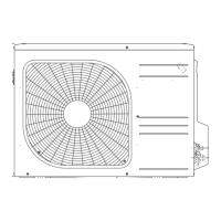
Provides unit dimensions, installation clearances, and component locations with diagrams.
Electrical wiring diagrams and component identification for indoor and outdoor units, including color coding.
Presents noise level data in decibels (dB) for indoor and outdoor units across various frequency bands.
Illustrates refrigerant piping layout and flow for cooling/heating cycles, identifying key components.
Defines operational limits for temperature, humidity, piping length, and voltage, including selection charts.
Cooling capacity table for DXK09ZJ-S based on varying indoor/outdoor air conditions.
Cooling capacity table for DXK12ZJ-S based on varying indoor/outdoor air conditions.
Cooling/heating capacity table for DXK18ZJ-S across different environmental conditions.
Guide and safety precautions for indoor unit installation, including location selection and mounting.
Installation procedures for the outdoor unit, covering safety, location, and mounting requirements.
Explains remote controller functions and button operations for unit control.
Details how to start and stop the unit using the ON/OFF button on the unit or remote.
Describes the auto restart feature, resuming operation after power interruption based on previous settings.
Instructions for modifying circuit boards or remote controllers for custom operation settings or compatibility.
Explains flap/louver adjustment for airflow direction control using the remote.
Details 3D auto operation for automatic airflow direction control based on temperature and operation.
Describes timer functions (comfortable, sleep, off) for scheduling unit operation.
Guides on setting indoor unit location to optimize airflow and prevent interference.
Explains heating operation components and control details, including fuzzy logic and defrosting.
Details cooling operation components and control logic, including fuzzy and automatic modes.
Explains automatic mode determination based on indoor/outdoor temperatures.
Describes various protective functions preventing damage or malfunction under specific conditions.
General cautions and safety guidelines before performing maintenance or troubleshooting.
Checklist of items to verify before troubleshooting to identify common issues.
Step-by-step guide to diagnose/resolve issues when the air conditioner fails to start.
Diagnostic flowchart for troubleshooting problems when the unit is running but not functioning correctly.
Table listing error codes, causes, and display patterns for diagnosing unit malfunctions.
Explains accessing/interpreting service data like error logs and protective stop history for diagnosis.
Procedures for inspecting/diagnosing issues with temperature sensors and their connections.
Graph of discharge pipe temperature vs. resistance for sensor diagnostics.
Steps to diagnose indoor fan motor faults, checking resistance and PCB issues.
Troubleshooting steps for current cut errors, indicating potential issues like compressor lock or faulty components.
Diagnosing current safe stop errors, possibly related to refrigerant, ventilation, or sensor issues.
Procedures for compressor overheating, potentially due to refrigerant, sensor, or valve issues.
Troubleshooting steps for signal transmission errors between indoor/outdoor units or PCB faults.
Guide for outdoor unit malfunctions: power, refrigerant, EEVs, and PCB issues.
Steps to diagnose outdoor fan motor errors, checking connections, resistance, and PCB.
Procedure for diagnosing rotor lock issues, related to compressor starting or power transistor faults.
Instructions for installing the optional wired remote controller, including wiring and mounting.
Details on installing the interface kit for external control devices or wired remote controllers.
Information on installing the Super Link E board for multi-unit control and external communication.