EasyManua.ls Logo

Mitsubishi Electric EHSC-MEC User Manual

Mitsubishi Electric EHSC-MEC
98 pages
To Next Page IconTo Next Page
Page #1 background imageLoading...
Page #1 background image
SERVICE MANUAL
CONTENTS
1. REFERENCE MANUAL
...................................
3
2. SAFETY PRECAUTION
...................................
4
3. SPECIFICATIONS
............................................
7
4. PART NAMES AND FUNCTIONS
................
10
5. OUTLINES AND DIMENSIONS
.....................
12
6. WIRING DIAGRAM
........................................
14
7. FIELD WIRING
...............................................
30
8. WATER SYSTEM DIAGRAM
.........................
32
9. CONTROLS
...................................................
35
10. TROUBLESHOOTING
...................................
55
11. DISASSEMBLY PROCEDURE
......................
72
12. SUPPLEMENTARY INFORMATION
.............
93
13. SERVICE AND MAINTENANCE
...................
94
Notes:
This manual describes ser-
vice data of Hydrobox only.
R410A
MAIN REMOTE
CONTROLLER
PARTS CATALOG (OCB571)
HYDROBOX
December 2018
HYDROBOX
No. OCH571
REVISED EDITION-D
OCH571 REVISED EDITION-C
is void.
Revision:
• Added
EHSC-MECR3.UK
,
EHSC-VM2CR3.UK,
EHSC-VM2ECR3.UK,
EHSC-VM6CR3.UK,
EHSC-VM6ECR3.UK,
EHSC-YM9CR3.UK,
EHSC-YM9ECR3.UK,
EHSC-TM9CR3.UK,
EHSD-MCR3.UK,
EHSD-MECR3.UK,
EHSD-VM2CR3.UK,
EHSD-YM9CR3.UK,
ERSC-MECR3.UK,
ERSC-VM2CR3.UK,
ERSD-VM2CR3.UK,
EHPX-VM2CR3.UK,
EHPX-VM6CR3.UK and
EHPX-YM9CR3.UK in
REVISED EDITION-D.
• Some descriptions have
been modified.
[Model Name]
EHSC-MEC
EHSC-VM2C
EHSC-VM2EC
EHSC-VM6C
EHSC-VM6EC
EHSC-YM9C
EHSC-YM9EC
EHSC-TM9C
EHSD-MC
EHSD-MEC
EHSD-VM2C
EHSD-YM9C
[Service Ref.]
Refer to page 2.
ERSC-MEC
ERSC-VM2C
ERSD-VM2C
EHPX-VM2C
EHPX-VM6C
EHPX-YM9C
Question and Answer IconNeed help?

Do you have a question about the Mitsubishi Electric EHSC-MEC and is the answer not in the manual?

Mitsubishi Electric EHSC-MEC Specifications

General IconGeneral
BrandMitsubishi Electric
ModelEHSC-MEC
CategoryHeat Pump
LanguageEnglish

Summary

Safety Precaution

Part Names and Functions

Wiring Diagram

Electrical Connections and Signal Logic

Presents detailed wiring diagrams, signal input/output tables, and DIP switch functions for various models.

Field Wiring

Power Supply Wiring Configurations

Details field wiring for hydrobox power supply, including 1-phase and 3-phase connections from outdoor units.

Water System Diagram

Controls

Troubleshooting

Error Code Diagnosis and Test Run Procedures

Outlines troubleshooting based on error codes, explains test runs, and malfunction diagnosis methods.

Self-Diagnosis and Component Part Checks

Details error codes, possible causes, and diagnostic actions, including checking component functions and resistance.

Inferior Phenomena Troubleshooting

Addresses common issues like blank displays, communication failures, and component faults with troubleshooting steps.

Component Part Checking Guidelines

Provides methods for checking component functions, including water pump characteristics and flow rates.

Disassembly Procedure

Hydrobox Component Removal Steps

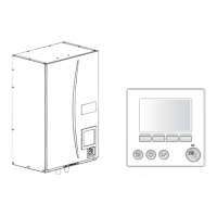
Step-by-step instructions for removing major hydrobox components like panels, electrical parts, pumps, sensors, and heat exchangers.

Related product manuals