Do you have a question about the Mitsubishi Electric EHSD-MEC.UK and is the answer not in the manual?
| Brand | Mitsubishi Electric |
|---|---|
| Model | EHSD-MEC.UK |
| Category | Water Heater |
| Language | English |
Lists available Hydrobox model names and their service references.
Lists service manuals for various outdoor units, referencing by Service Ref. number.
Details critical safety precautions for installation, operation, and maintenance to prevent injury or damage.
Lists specific tools required for handling R410A refrigerant, essential for safe and correct operation.
Specifies essential tools for servicing R410A systems, ensuring proper procedures.
Provides detailed technical specifications for various Hydrobox models, including dimensions, electrical data, and temperature ranges.
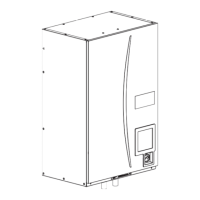
Illustrates and lists key components of the Hydrobox for both split and packaged systems.
Presents detailed technical drawings of the Hydrobox, showing dimensions and connection points for various models.
Specifies the necessary clearances and environmental conditions for servicing the hydrobox.
Illustrates the electrical wiring for specific Hydrobox models, detailing signal inputs and outputs.
Provides detailed wiring diagrams for a range of Hydrobox models, covering signal inputs, outputs, and component connections.
Details the electrical wiring specific to the EHSC-VM6C and EHSC-VM6EC Hydrobox models.
Illustrates the electrical wiring configurations for EHSC-YM9C, EHSC-YM9EC, and EHPX-YM9C Hydrobox models.
Details the electrical wiring for the EHSC-TM9C Hydrobox model, including signal inputs and outputs.
Explains the function and settings of DIP switches on the FTC printed circuit board for various Hydrobox models.
Illustrates the 1-phase electrical wiring between the hydrobox and outdoor unit, including breaker and cable specifications.
Details wiring requirements for hydrobox and outdoor units when powered by separate sources, including 1-phase and 3-phase configurations.
Illustrates the internal water circuit of the Hydrobox for different model types, showing component connections.
Depicts various local system configurations for temperature control, including diagrams for 1-zone, 2-zone, and boiler integration.
Provides step-by-step instructions for filling the primary heating circuit with water and anti-freeze, ensuring proper system pressurization.
Details the procedure for safely draining the hydrobox, including warnings about hot water and specific component draining.
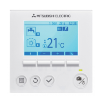
Explains the main controller's interface, including buttons, screen layout, and various operational icons.
Guides through the initial settings and configuration of the main controller upon first power-up.
Describes how to access the main settings menu, differentiating between user and installer levels for parameter adjustment.
Provides a hierarchical tree structure for navigating the main controller's menu options and settings.
Expands on the controller menu, detailing functions like manual operation, auxiliary settings, and energy monitoring.
Outlines the service menu, accessible by installers, for advanced functions like manual operation and function settings.
Explains how to adjust thermistor readings and configure auxiliary settings for pumps, heaters, and mixing valves.
Details settings for mixing valve control, flow sensor configuration, heat source selection, and pump speed adjustment.
Covers operational settings for heating modes, including flow temperature ranges, room control, and freeze stat functions.
Explains how to configure the energy monitor settings for electrical energy and heat energy consumption.
Details settings for external inputs, displays running information, and lists thermistor readings for various sensors.
Shows a summary of entered settings, how to view error history, and procedures for setting or resetting the password.
Explains how to reset the password, perform a manual reset of settings, and use an SD card for controller configuration.
Lists request codes for the service menu, detailing parameters, ranges, and units for system monitoring and diagnostics.
Describes how to activate and deactivate indoor unit-only operation and emergency operation modes for heaters and boilers.
Explains how to interpret error codes displayed on the controller for diagnosing and resolving issues.
Details possible causes and diagnostic actions for circulation water temperature overheat errors (L3).
Covers troubleshooting for thermistor failures (P1/P2/L5/LD) and circulation water freeze protection (L6) errors.
Addresses troubleshooting for heating operation errors (L8) and low primary circuit flow rate detection (L9).
Details troubleshooting steps for various error codes related to boiler, DHW, cooling, and communication failures.
Focuses on troubleshooting communication failures between controllers and units, including reception and transmission errors.
Addresses troubleshooting for main controller failures (E1/E2) and wireless communication issues (J0, J1-J8, J9).
Diagnoses common issues related to the main controller display and FTC board LEDs, providing solutions for blank screens or incorrect displays.
Covers troubleshooting for FTC board issues, wiring faults, SD card problems, and common faults with 3-way valves.
Addresses performance problems like slow heating, DHW temperature drops, and failure to reach set temperatures, including booster heater and valve checks.
Discusses troubleshooting for 2-zone control issues, noise, unexpected pump operation, milky water, and standby heating.
Covers troubleshooting for automatic mode switching after power recovery, cooling performance, and incorrect energy monitor readings.
Displays performance curves for water circulation pumps across different EHSC, EHSD, ERSC, ERSD, and EHPX series models.
Details how to check the functionality of the booster heater and its associated relay, including resistance measurements.
Explains how to check thermistors and flow sensors by measuring resistance and observing output signals.
Provides graphs and tables showing the resistance characteristics of various thermistors at different temperatures.
Illustrates the connections on the FTC controller board, detailing terminals for various inputs, outputs, and sensors.
Provides step-by-step instructions and illustrations for removing the front panel and the main remote controller.
Details the process for removing electrical parts like earth leakage circuit breakers, contactors, terminal blocks, and the controller board.
Explains how to swing the control box to the front for easier access to internal components.
Provides instructions for removing the water pump and pump valve for E*S* series Hydrobox models.
Details the procedure for removing the water pump and pump valve specifically for EHPX series Hydrobox models.
Guides on how to remove the flow sensor, including disconnecting its wiring and detaching mounting nuts.
Explains the steps for removing the booster heater and associated parts for E*S* series Hydrobox models.
Details the procedure for removing the booster heater and related components for EHPX series Hydrobox models.
Provides instructions for removing the plate heat exchanger and associated water circuit parts for ERSC series models.
Continues the procedure for removing the plate heat exchanger for ERSC series, detailing strainer valve and pipe removal.
Details the process of removing the plate heat exchanger and strainer valve for EHSC series Hydrobox models.
Explains how to remove the plate heat exchanger and associated piping for E*SD series models.
Continues the plate heat exchanger removal steps for E*SD series, focusing on water coil cover and base removal.
Details the process for removing the strainer and its components for ERS* and EHS* series Hydrobox models.
Provides instructions for removing the strainer and associated parts for EHPX series Hydrobox models.
Guides on removing the manometer, pressure relief valve, and automatic air vent, including specific connection and fitting details.
Details the procedure for removing the automatic air vent and its associated flare joint.
Explains the steps for removing the expansion vessel, including detaching flare joints and metal supports.
Details how to remove the primary circuit drain cock from the Hydrobox.
Provides instructions for removing thermistors TH1, TH2, THW1, and THW2, including connector disconnection and holder removal.
Details the steps for removing the drain pan and its associated components for ERS* series Hydrobox models.
Explains the steps for detaching and attaching quick joints, including O-ring replacement and clip installation.
Provides guidance on using loctite and remover, and lists recommended tightening torques for various parts and fittings.
Covers refrigerant collecting procedures for split systems and details the back-up operation of the boiler for heating.
Explains how to configure systems for multiple outdoor unit control and the role of the hydrobox as a slave unit.
Provides forms for recording engineering settings and maintenance logs, aiding in future system configuration and troubleshooting.
Lists various parameters with default and field settings, covering heating, cooling, DHW, and energy monitoring for engineer reference.
Details the annual maintenance schedule, log book usage, and a list of parts requiring regular replacement or inspection.