EasyManua.ls Logo

Mitsubishi Electric EHST17D-VM2D - User Manual

Mitsubishi Electric EHST17D-VM2D
92 pages
Print Icon
To Next Page IconTo Next Page
Loading...
SERVICE MANUAL
CONTENTS
1. REFERENCE MANUAL
...................................
3
2. SAFETY PRECAUTION
...................................
4
3. SPECIFICATIONS
............................................
6
4. PART NAMES AND FUNCTIONS
..................
9
5. OUTLINES AND DIMENSIONS
......................
11
6. WIRING DIAGRAM
........................................
13
7. FIELD WIRING
...............................................
19
8. WATER SYSTEM DIAGRAM
.........................
23
9. CONTROLS
...................................................
27
10. TROUBLESHOOTING
...................................
48
11. DISASSEMBLY PROCEDURE
......................
65
12. SUPPLEMENTARY INFORMATION
.............
86
13. SERVICE AND MAINTENANCE
...................
87
Note:
This manual describes service
data of cylinder unit only.
PARTS CATALOG (OCB714)
CYLINDER UNIT
CYLINDER UNIT
MAIN REMOTE
CONTROLLER
March 2020
No. OCH714
REVISED EDITION-A
[Model Name]
EHST17D-VM2D
ERST17D-VM2D
EHST20D-MED
EHST20D-VM2D
EHST20D-VM6D
EHST20D-YM9D
EHST20D-YM9ED
EHST20D-TM9D
ERST20D-VM2D
EHST30D-MED
EHST30D-VM6ED
EHST30D-YM9ED
EHST30D-TM9ED
ERST30D-VM2ED
EHST20C-MED
EHST20C-VM2D
EHST20C-VM6D
[Service Ref.]
Refer to page 2.
EHST20C-YM9D
EHST20C-YM9ED
EHST20C-TM9D
ERST20C-VM2D
EHST30C-MED
EHST30C-VM6ED
EHST30C-YM9ED
EHST30C-TM9ED
ERST30C-VM2ED
EHPT17X-VM2D
EHPT17X-VM6D
EHPT17X-YM9D
ERPT17X-VM2D
EHPT20X-MED
EHPT20X-VM6D
EHPT20X-YM9D
EHPT20X-YM9ED
EHPT20X-TM9D
EHPT20X-MHEDW
ERPT20X-MD
ERPT20X-VM2D
ERPT20X-VM6D
EHPT30X-MED
EHPT30X-YM9ED
ERPT30X-VM2ED
Revision:
Added packaged models
Some descriptions have
been modified
in REVISED
EDITION-A
.
OCH714 is void.

Table of Contents

Question and Answer IconNeed help?

Do you have a question about the Mitsubishi Electric EHST17D-VM2D and is the answer not in the manual?

Summary

1 REFERENCE MANUAL

2 SAFETY PRECAUTION

Safety Symbols and Service Tools

Explanation of safety symbols and essential tools for refrigerant handling.

3 SPECIFICATIONS

4 PART NAMES AND FUNCTIONS

5 OUTLINES AND DIMENSIONS

Technical Drawings and Unit Dimensions

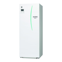
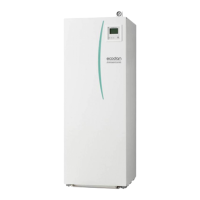
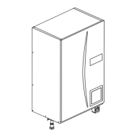
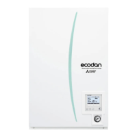
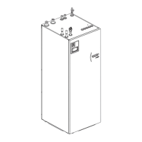
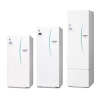
Provides technical drawings and dimensions for various unit models.

Service Access Diagrams

Illustrates required space for service access around the unit.

6 WIRING DIAGRAM

Wiring Diagrams for Various Models

Wiring diagrams for different E**T***, EH*T***, and E*PT* models.

DIP Switch Functions

Explains the function of each DIP switch setting on the circuit board.

7 FIELD WIRING

Cylinder Unit Powered via Outdoor Unit

Details electrical connections when the cylinder unit is powered by the outdoor unit.

Cylinder Unit Powered by Independent Source

Details electrical connections when the cylinder unit has an independent power supply.

8 WATER SYSTEM DIAGRAM

Water System Diagram for Packaged Models

Water system diagram for packaged model systems.

Water System Diagram for Split Models

Water system diagram for split model systems.

Local System Configurations

Temperature Control System Diagrams

Diagrams illustrating local system configurations for temperature control.

Cylinder Unit Filling and Draining Procedures

Primary Circuit Filling

Procedure for filling the primary circuit of the cylinder unit with water.

Potable;DHW Circuit Filling

Procedure for filling the potable/DHW circuit of the cylinder unit with water.

Cylinder Unit Draining Procedure

Procedure for draining the cylinder unit, including safety warnings.

9 CONTROLS

Main Remote Controller Overview

Overview of the main remote controller's buttons, display icons, and functions.

Remote Controller Settings Navigation

Steps for initial setup and setting parameters via the main remote controller.

Service Menu Functions

Details functions available to installers and service engineers.

Auxiliary Settings for Components

Economy Settings for Pump

Adjusts pump stop timing for energy saving after operation.

Electric Heater Settings

Configures booster and immersion heater operation timing.

Mixing Valve and Flow Sensor Settings

Adjusts mixing valve timing and flow sensor parameters.

Operation Settings

Heating Operation Settings

Configures heating parameters like flow temperature and room temperature control.

Freeze Stat and Cold Weather Functions

Settings for preventing freezing and managing operation in cold conditions.

Floor Dry Up Function

Manages hot water temperature for concrete drying in specific heating systems.

Energy Monitor Settings

External Inputs, Running Information, and Thermistors

External Input Settings

Configuration for external inputs like demand control and outdoor thermostat.

Running Information and Thermistor Readings

Displays running unit data and thermistor readings for diagnostics.

System Settings and Diagnostics

Settings Summary, Error History, and Password

Summary of settings, error history log, and password protection features.

SD Card Data Management

Procedures for using an SD card to save and load unit settings.

Unit Operation Modes

Indoor Unit Only Operation

Explains how to operate the indoor unit independently of the outdoor unit.

Emergency Operation Mode

Details how to operate the unit in emergency mode without outdoor unit or remote controller.

10 TROUBLESHOOTING

Troubleshooting Overview and Diagnosis Methods

Overview of self-diagnosis, test runs, and malfunction diagnosis via remote controller.

Self Diagnosis and Error Code Actions

Detailed guide for self-diagnosis and corrective actions based on error codes.

Troubleshooting by Phenomenon

Guidance for diagnosing issues based on observed symptoms rather than error codes.

10-6. Checking Component Parts Function

Water Circulation Pump Checks

Details how to check the function and flow rate of the primary circuit water circulation pump.

Booster Heater and Electrical Component Checks

Instructions for checking booster heater resistance, ELBs, and relays.

3-Way Valve, Pressure Sensor, and Thermistor Checks

Procedures for checking 3-way valve operation, pressure sensors, and thermistors.

Test Point Diagram for FTC Controller

11 DISASSEMBLY PROCEDURE

Unit Panel and Control System Access

Procedures for removing the front panel and remote controller assembly.

Electrical Components and Control Box Removal

Steps for removing electrical parts and the control box.

Water System Components Removal

Procedures for removing water pumps, valves, and strainers.

Booster Heater and Heat Exchanger Removal

Procedures for removing the booster heater and plate heat exchanger.

Notes on Part Replacement

12 SUPPLEMENTARY INFORMATION

Refrigerant Collection and Boiler Backup Setup

Information on refrigerant collection and boiler backup heating configuration.

13 SERVICE AND MAINTENANCE

Engineers Forms for Settings Record

Forms for recording settings changes during commissioning and maintenance.

Annual Maintenance Log Book

Log book for recording annual maintenance activities and part replacements.

Mitsubishi Electric EHST17D-VM2D Specifications

General IconGeneral
BrandMitsubishi Electric
ModelEHST17D-VM2D
CategoryAir Conditioner
LanguageEnglish

Related product manuals