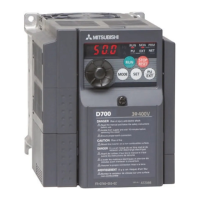
What to do if Mitsubishi Electric FR-D740-2.2K Inverter shows PU disconnection?
- LLisa MorrowSep 6, 2025
This function stops the inverter output if communication between the inverter and PU is suspended. Connect the parameter unit cable securely.

What to do if Mitsubishi Electric FR-D740-2.2K Inverter shows PU disconnection?
This function stops the inverter output if communication between the inverter and PU is suspended. Connect the parameter unit cable securely.
What to do if Mitsubishi Electric FR-D740-2.2K has overcurrent trip during acceleration?
If the inverter output current reaches or exceeds approximately 200% of the rated current during acceleration, the protective circuit activates and shuts off the inverter output. You can increase the acceleration time. If "E.OC1" is always lit at starting, disconnect the motor and start the inverter. Check for output short-circuit/ground fault and set 50Hz in Pr. 3 Base frequency.
What causes Mitsubishi Electric FR-D740-2.2K Inverter overload trip and how to fix it?
The inverter output stops if the temperature of the output transistor element exceeds the protection level when a current not less than the inverter rated current flows and overcurrent trip does not occur (200% or less). To resolve this, increase the acceleration/deceleration time.
What does output current detection value exceeded mean on Mitsubishi Electric FR-D740-2.2K?
This function is activated when the output current exceeds the Pr. 150 Output current detection level setting. Check the settings of Pr. 150 Output current detection level.
What to do if my Mitsubishi Electric FR-D740-2.2K is showing overcurrent trip during constant speed?
If your Mitsubishi Electric Inverter is showing an overcurrent trip during constant speed operation, make sure the load is stable. Also, check the wiring for any output short circuits or ground faults. Try lowering the stall prevention operation level and activating both the stall prevention operation and the fast-response current limit operation (Pr.156).
How to resolve analog input fault on Mitsubishi Electric Inverter?
An analog input fault appears if voltage(current) is input to terminal 4 when the setting in Pr.267 Terminal 4 input selection and the setting of voltage/current input switch are different. Give a frequency command by current input or set Pr. 267 Terminal 4 input selection, and voltage/current input switch to voltage input.
What happens when Mitsubishi Electric FR-D740-2.2K Inverter has output phase loss?
If one of the three phases (U, V, W) on the inverter's output side (load side) is lost during inverter operation, the inverter stops the output. Ensure that the cables are wired properly.
What to do if my Mitsubishi Electric FR-D740-2.2K shows overcurrent trip during deceleration or stop?
If your Mitsubishi Electric Inverter shows an overcurrent trip during deceleration or at a stop, try these steps: Increase the deceleration time. Check the wiring, looking for output short circuits or ground faults. Verify that the mechanical brake isn't activating too early. Also, consider lowering the stall prevention operation level and activating the stall prevention operation and the fast-response current limit operation (Pr.156).
What causes regenerative overvoltage trip during constant speed on Mitsubishi Electric Inverter?
If regenerative energy causes the inverter's internal main circuit DC voltage to reach or exceed the specified value, the protective circuit is activated to stop the inverter output. Ensure that you keep load stable.
What causes motor overload trip on Mitsubishi Electric Inverter?
The electronic thermal relay function in the inverter detects motor overheat due to overload or reduced cooling capability during low-speed operation. To resolve this, reduce the load weight.
| Brand | Mitsubishi Electric |
|---|---|
| Model | FR-D740-2.2K |
| Category | Inverter |
| Language | English |
Covers environmental standards, temperature, humidity, dust, and vibration considerations for inverter installation.
Provides the terminal connection diagram for the inverter's main and control circuits.
Details the terminal layout, specifications, and wiring for the main circuit of various inverter models.
Discusses leakage currents, countermeasures, and line-to-line leakage currents.
Covers general safety precautions, wiring, handling, and installation guidelines to prevent product damage or life shortening.
Explains how to provide system failsafe by using inverter status output signals to prevent accidents.
Provides a comprehensive list of all parameters, their settings, initial values, and refer pages.
Details motor overheat protection using electronic thermal O/L relay or PTC thermistor, and applied motor selection.
Describes how to assign functions to input and output terminals, communication, and safety stop signals.
Explains automatic restart after power failure and power-failure deceleration stop functions.
Details retry functions, phase loss protection, and earth fault detection at start.
Details reset selection, disconnected PU detection, PU stop selection, parameter write disable, and password functions.
Explains the procedures to reset the inverter after a fault or warning occurs.
Provides a table of fault and alarm codes displayed on the operation panel, with corresponding names and refer pages.
Details common causes for error messages, warnings, and faults, along with recommended corrective actions.


 Loading...