14
Installation
4
en
4.3 Water Pipe Work
Note: Prevent the eld piping from straining the piping on the hydrobox by
xing it to a wall or applying other methods.
Hot Water Pipework
The function of the following safety components of the hydrobox should be
checked on installation for any abnormalities;
• Pressure relief valve
• Expansion vessel pre-charge (gas charge pressure)
The instruction on the following pages regarding safe discharge of hot water from
Safety devices should be followed carefully.
• The pipework will become very hot, so should be insulated to prevent burns.
• When connecting pipework, ensure that no foreign objects such as debris or the
like enter the pipe.
Insulation of Pipework
•
All exposed water pipework should be insulated to prevent unnecessary heat loss
and condensation. To prevent condensate entering the hydrobox, the pipework
and connections at the top of the hydrobox should be carefully insulated.
• Cold and hot water pipework should not be run close together where possible, to
avoid unwanted heat transfer.
•
Pipework between outdoor heat pump unit and hydrobox should be insulated with
suitable pipe insulation material with a thermal conductivity of ≤ 0.04 W/m.K.
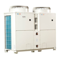
<Figure 4.3.1>
Factory-fitted pressure relief valve
(G1/2” female connection)
Discharge to drain
(pipe MUST responsibly be tted by installer).
Safety Device Connections
The hydrobox contains a pressure relief valve. (see <Figure 4.3.1>) The connec-
tion size is G1/2” female. The installer MUST responsibly connect appropriate
discharge pipework from this valve in accordance with local and national regula-
tions.
Failure to do so will result in discharge from the pressure relief valve directly into
the hydrobox and cause serious damage to the product.
All pipework used should be capable of withstanding discharge of hot water.
Relief valves should NOT be used for any other purpose, and their discharges
should terminate in a safe and appropriate manner in accordance with local regu-
lation requirements.
Note: Beware that the manometer and the pressure relief valve are NOT
strained on its capillary side and on its inlet side respectively.
If a pressure relief valve is added, it is essential that no check valve
or isolation valve is tted between the hydrobox connection and the
added pressure relief valve (safety matter).
Hydraulic Filter Work (ONLY EHPX series)
Install a hydraulic lter or strainer (local supply) at the water intake (“Pipe E” in
Table 3.3, also see associated schematic Fig. 3.5)
Pipework Connections
Connections to the hydrobox should be made using the G1-1/2 nut as appropriate.
(The hydrobox has G1-1/2 (male) thread connections.)
Please apply a gasket not to leak water.
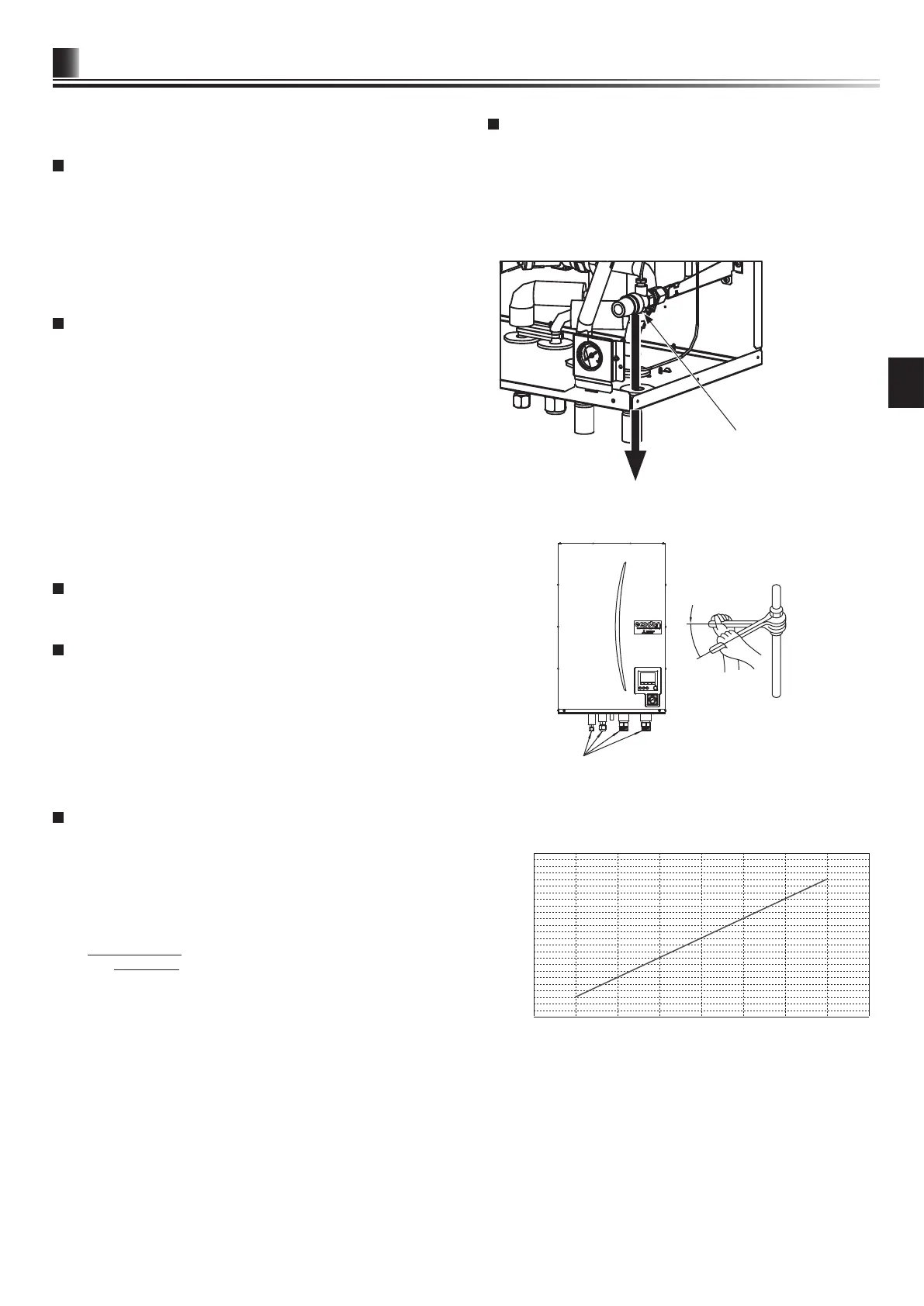
Use two wrenches to tighten piping connection (see <Figure 4.3.2>).
<Figure 4.3.2>
Pipes
0
0
5
10
15
20
25
50 100 150 200 250 300 350
Expansion vessel sizing
Expansion vessel volume [L]
System water volume [L]
<Figure 4.3.3>
Sizing Expansion Vessels
Expansion vessel volume must t the local system water volume.
To size an expansion vessel both for the heating and cooling circuits the following
formula and graph can be used.
When the necessary expansion vessel volume exceeds the volume of an built-in
expansion vessel, install an additional expansion vessel so that the sum of the
volumes of the expansion vessels exceeds the necessary expansion vessel volume.
* For installation of an E*S*-*M*EC model, provide and install an expansion
vessel in the eld as the model does not come tted with an expansion vessel.
V =
ε × G
1 −
P
¹
+ 0.098
P
²
+ 0.098
Where;
V : Necessary expansion vessel volume [L]
ε : Water expansion coefcient
G : Total volume of water in the system [L]
P
¹
: Expansion vessel setting pressure [MPa]
P
²
: Max. pressure during operation [MPa]
Graph to the right is for the following values
ε : at 70 °C = 0.0229
P
¹
: 0.1 MPa
P
²
: 0.3 MPa
*A 30% safety margin has been added.