EasyManua.ls Logo

Mitsubishi Electric MCFH-24NV-E3 User Manual

Mitsubishi Electric MCFH-24NV-E3
72 pages
To Next Page IconTo Next Page
Page #1 background imageLoading...
Page #1 background image
SERVICE MANUAL
Wireless type
Models
MCFH-13NV-
(WH)
·MUCFH-13NV-
MCFH-18NV-
(WH)
·MUCFH-18NV-
·MUCFH-18NV-
MCFH-24NV-
(WH)
·MUCFH-24NV-
E3E3
E4
E3E3
E4E4
No. OB267
REVISED EDITION-A
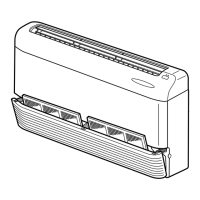
(When installed on the ceiling)
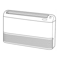
(When installed on the floor)
FLOOR AND CEILING TYPE AIR CONDITIONERS
• Refer to service manual OB212 for MCFH-13/18/24/NV- , MUCFH-13/18/24/NV- ,
MCFH-13/18/24/NV- and MUCFH-13/18/24/NV- .
• Refer to service manual OB240 for MCFH-13NV- and MUCFH-13NV- .
• Refer to service manual OB185 REVISED EDITION-C for MCFH-13NV- or MCFH-18NV- is
connected with MXZ-32NV- .
• Refer to service manual OB227 REVISED EDITION-B for MCFH-13NV- or MCFH-18NV- is
connected with MXZ-32RV- .
• Refer to service manual OB254 for MCFH-13NV- or MCFH-18NV- is connected with
MXZ-32SV- .
As for parts lists, all sub number’s series are included.
E1
E3E4
E1
E3E4
E2
E3E4
E3E3
E2E2
E1E1
Revision:
MUCFH-18NV- has been added.
MUCFH-18NV- MUCFH-18NV-
•Path of outdoor heat exchanger has changed .
•Temperature range of high pressure protection has
changed.
•Please void OB267.
E4E3
E4
CONTENTS
1. TECHNICAL CHANGES ····································2
2. PART NAMES AND FUNCTIONS······················2
3. SPECIFICATION·················································5
4. NOISE CRITERIA CURVES·······························6
5. OUTLINES AND DIMENSIONS ·························7
6. WIRING DIAGRAM ··········································10
7. REFRIGERANT SYSTEM DIAGRAM··············14
8. PERFORMANCE CURVES······························16
9. MICROPROCESSOR CONTROL ····················32
10. SERVICE FUNCTIONS·····································41
11. TROUBLESHOOTING······································42
12. DISASSEMBLY INSTRUCTIONS·····················55
13. PARTS LIST······················································63
14. OPTIONAL PARTS ······················BACK COVER
OB267--1.qxp 01.12.19 2:58 PM Page 1

Questions and Answers:

Mitsubishi Electric MCFH-24NV-E3 Specifications

General IconGeneral
ModelMCFH-24NV-E3
CategoryAir Conditioner
ManufacturerMitsubishi Electric
Cooling Capacity24, 000 BTU/h
Heating Capacity27, 000 BTU/h
Phase1
Frequency60 Hz
RefrigerantR410A
Voltage208/230V

Summary

Service Manual Overview

Wireless Type Models

Lists the available indoor unit models for the service manual.

Technical Changes Summary

Details revisions and modifications made to the product.

Indoor Unit Part Names and Functions

Identifies and describes the components of the indoor unit.

Indoor Unit Accessories

Lists the included accessories for the indoor unit.

Outdoor Unit Information

Outdoor Unit Components

Identifies the components of the outdoor unit.

Outdoor Unit Accessories

Lists the included accessories for the outdoor unit.

Remote Controller Operation Guide

Remote Controller Buttons and Functions

Details the function of each button on the remote controller.

Technical Specifications

Indoor Model Specifications

Provides technical data and ratings for indoor units.

Outdoor Model Specifications

Provides technical data and ratings for outdoor units.

Noise Criteria Curves

Physical Dimensions and Clearances

Indoor Unit Dimensions

Shows physical dimensions and installation clearances for indoor units.

Outdoor Unit Dimensions and Clearances

Shows physical dimensions and required clearances for outdoor units.

Wiring Diagrams

Indoor Unit Wiring Diagram

Illustrates the electrical connections for the indoor unit.

Outdoor Unit Wiring Diagram

Illustrates the electrical connections for the outdoor unit.

Refrigerant System Diagrams

MCFH-13NV Refrigerant Circuit

Diagram of the refrigerant circuit for the MCFH-13NV model.

MCFH-18NV Refrigerant Circuit

Diagram of the refrigerant circuit for the MCFH-18NV model.

MCFH-24NV Refrigerant Circuit

Diagram of the refrigerant circuit for the MCFH-24NV model.

Refrigerant Piping Specifications

Details refrigerant piping length and height difference limits.

Additional Refrigerant Charge

Instructions for adding refrigerant for longer piping.

Performance Data and Curves

Cooling Performance Curves

Graphs illustrating cooling performance under various conditions.

Heating Performance Curves

Graphs illustrating heating performance under various conditions.

Outdoor Unit Pressure and Current (Cooling)

Data on outdoor unit pressure and current during cooling.

Outdoor Unit Current (Heating)

Data on outdoor unit current during heating.

Detailed Performance Data

Cooling Performance Data (220V)

Table of cooling performance data for 220V operation.

Cooling Performance Data (240V)

Table of cooling performance data for 240V operation.

Heat Operation Performance Data

Table of heating performance data.

Control System Operation

Microprocessor Control Overview

Explanation of the microprocessor control system.

Indoor Unit Display Indicators

Describes the meaning of the indoor unit's operation indicator lamp.

I FEEL CONTROL Mode Operation

Details on operating in I FEEL CONTROL modes.

Dry Mode I FEEL CONTROL

Specific operational details for the DRY mode.

Heat Mode I FEEL CONTROL

Specific operational details for the HEAT mode.

Operational Features and Controls

Cold Air Prevention Control

Mechanism to prevent cold air discharge during heating.

High Pressure Protection

System protection against high discharge pressure.

R.V. Coil Control

Control logic for the R.V. coil.

Defrosting and Timer Operations

Defrosting Operation Details

Conditions and timing for defrosting operation.

Timer Operation Instructions

Steps for setting and canceling timers.

Special Operations

Emergency and Test Operation

Procedures for emergency or test run operation.

Auto Restart Function

How the unit restarts automatically after power loss.

Service Functions

Compulsory Defrosting Mode

Forcing defrost mode for service purposes.

Defrost Setting Modification

Changing defrost interval and temperature settings.

Timer Short Mode

Shortening timer delays for service.

P.C. Board Modification for Multi-Units

Modifying PC boards for multiple remote controllers.

Troubleshooting Guide

General Troubleshooting Cautions

Important safety and handling notes before troubleshooting.

Troubleshooting Procedure Steps

General steps for diagnosing unit problems.

Troubleshooting Flowchart

Decision tree for diagnosing unit operation issues.

Troubleshooting Check Table

Table correlating indicator flashes to symptoms and checks.

Main Part Trouble Criteria

Resistance checks for key operational components.

Indoor Fan Motor Diagnosis

Steps to diagnose issues with the indoor fan motor.

Remote Controller and Receiver Diagnosis

Diagnosing problems with the remote and receiver.

Indoor Electronic Control P.C. Board Check

Diagnosing issues with the indoor electronic control board.

Outdoor Unit Initial Checks

Initial troubleshooting steps for the outdoor unit.

Outdoor Unit Compressor and Fan Checks

Detailed checks for the outdoor compressor and fan motor.

Mis-wiring and Serial Signal Error Check

Diagnosing wiring and serial communication problems.

Outdoor Unit Operation and R.V. Coil Checks

Verifying operational modes and R.V. coil function.

Outdoor Thermistor Check

Checks for defrost and ambient thermistors.

Diagrams and Component Locations

Indoor Electronic Control P.C. Board Layout

Diagram of the indoor P.C. board with test points.

Outdoor Deicer P.C. Board Layout

Diagram of the outdoor deicer P.C. board.

Disassembly Instructions

Indoor Unit Disassembly

Steps for disassembling the indoor unit components.

Removing Indoor Heat Exchanger

Steps to remove the indoor heat exchanger.

Outdoor Unit Disassembly

Removing Outdoor Unit Cabinet

Steps to remove the outdoor unit cabinet.

Removing Outdoor Deicer P.C. Board

Steps to remove the outdoor deicer P.C. board.

Removing Outdoor Fan Motor

Steps to remove the outdoor fan motor.

Removing Compressor

Steps to remove the compressor.

Parts Lists

Indoor Unit Structural Parts

List of structural components for indoor units.

Indoor Unit Electrical Parts

List of electrical components for indoor units.

Indoor Unit Accessories

List of accessories for indoor units.

Outdoor Unit Structural Parts (MCFH-13NV)

List of structural components for MCFH-13NV outdoor units.

Outdoor Unit Electrical Parts (MCFH-13NV)

List of electrical parts for MCFH-13NV outdoor units.

Outdoor Unit Accessories (MCFH-13NV)

List of accessories for MCFH-13NV outdoor units.

Outdoor Unit Structural Parts (MCFH-18NV)

List of structural components for MCFH-18NV outdoor units.

Outdoor Unit Structural Parts (MCFH-24NV)

List of structural components for MCFH-24NV outdoor units.

Outdoor Unit Structural Parts (MCFH-24NV) - Continued

List of structural components for MCFH-24NV outdoor units.

Optional Parts

Air Cleaning Filter Information

Details and replacement information for the air cleaning filter.

Deodorizing Filter Information

Details and replacement information for the deodorizing filter.

Related product manuals