EasyManua.ls Logo

Mitsubishi Electric MCFH-24NV-WH User Manual

Mitsubishi Electric MCFH-24NV-WH
72 pages
To Next Page IconTo Next Page
Page #1 background imageLoading...
Page #1 background image
SERVICE MANUAL
Wireless type
Models
MCFH-13NV-
(WH)
·MUCFH-13NV-
MCFH-18NV-
(WH)
·MUCFH-18NV-
·MUCFH-18NV-
MCFH-24NV-
(WH)
·MUCFH-24NV-
E3E3
E4
E3E3
E4E4
No. OB267
REVISED EDITION-A
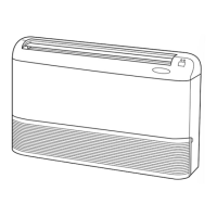
(When installed on the ceiling)
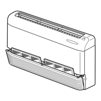
(When installed on the floor)
FLOOR AND CEILING TYPE AIR CONDITIONERS
• Refer to service manual OB212 for MCFH-13/18/24/NV- , MUCFH-13/18/24/NV- ,
MCFH-13/18/24/NV- and MUCFH-13/18/24/NV- .
• Refer to service manual OB240 for MCFH-13NV- and MUCFH-13NV- .
• Refer to service manual OB185 REVISED EDITION-C for MCFH-13NV- or MCFH-18NV- is
connected with MXZ-32NV- .
• Refer to service manual OB227 REVISED EDITION-B for MCFH-13NV- or MCFH-18NV- is
connected with MXZ-32RV- .
• Refer to service manual OB254 for MCFH-13NV- or MCFH-18NV- is connected with
MXZ-32SV- .
As for parts lists, all sub number’s series are included.
E1
E3E4
E1
E3E4
E2
E3E4
E3E3
E2E2
E1E1
Revision:
MUCFH-18NV- has been added.
MUCFH-18NV- MUCFH-18NV-
•Path of outdoor heat exchanger has changed .
•Temperature range of high pressure protection has
changed.
•Please void OB267.
E4E3
E4
CONTENTS
1. TECHNICAL CHANGES ····································2
2. PART NAMES AND FUNCTIONS······················2
3. SPECIFICATION·················································5
4. NOISE CRITERIA CURVES·······························6
5. OUTLINES AND DIMENSIONS ·························7
6. WIRING DIAGRAM ··········································10
7. REFRIGERANT SYSTEM DIAGRAM··············14
8. PERFORMANCE CURVES······························16
9. MICROPROCESSOR CONTROL ····················32
10. SERVICE FUNCTIONS·····································41
11. TROUBLESHOOTING······································42
12. DISASSEMBLY INSTRUCTIONS·····················55
13. PARTS LIST······················································63
14. OPTIONAL PARTS ······················BACK COVER
OB267--1.qxp 01.12.19 2:58 PM Page 1

Questions and Answers:

Mitsubishi Electric MCFH-24NV-WH Specifications

General IconGeneral
BrandMitsubishi Electric
ModelMCFH-24NV-WH
CategoryAir Conditioner
LanguageEnglish

Summary

TECHNICAL CHANGES

PART NAMES AND FUNCTIONS

INDOOR UNIT PARTS

Identifies and describes components of the indoor unit.

OUTDOOR UNIT PARTS

Identifies and describes components of the outdoor unit.

SPECIFICATION

NOISE CRITERIA CURVES

OUTLINES AND DIMENSIONS

INDOOR UNIT DIMENSIONS

Provides detailed measurements and installation space for the indoor unit.

OUTDOOR UNIT DIMENSIONS

Provides detailed measurements and installation space for the outdoor unit.

WIRING DIAGRAM

INDOOR UNIT WIRING DIAGRAMS

Illustrates the electrical connections for the indoor unit.

OUTDOOR UNIT WIRING DIAGRAMS

Illustrates the electrical connections for the outdoor unit.

REFRIGERANT SYSTEM DIAGRAM

INDOOR UNIT REFRIGERANT FLOW

Shows the refrigerant path within the indoor unit.

OUTDOOR UNIT REFRIGERANT FLOW

Shows the refrigerant path within the outdoor unit.

PERFORMANCE CURVES

COOLING PERFORMANCE DATA

Graphs showing cooling capacity, total input vs. temperatures.

TEMPERATURE MEASUREMENT GUIDE

Instructions for measuring indoor/outdoor air temperatures for performance analysis.

HEATING PERFORMANCE DATA

Graphs showing heating capacity, total input vs. temperatures.

MICROPROCESSOR CONTROL

WIRELESS REMOTE CONTROLLER OVERVIEW

Explains the functions and layout of the wireless remote controller.

INDOOR UNIT INDICATOR LAMPS

Describes the meaning of the operation indicator lamp indications.

"I FEEL CONTROL" MODES

Details the operation modes based on room temperature.

SERVICE FUNCTIONS

COMPULSORY DEFROSTING MODE

Activates defrosting mode for service purposes.

DEFROST SETTING ADJUSTMENT

Modifies defrost interval and temperature settings.

TIMER SHORT MODE CONFIGURATION

Shortens timer operation delays for service.

P.C. BOARD MODIFICATION FOR MULTI-UNIT OPERATION

Modifies PC boards for individual unit control in multi-unit systems.

AUTO RESTART FUNCTION RELEASE

Disables the auto restart function for specific service needs.

TROUBLESHOOTING

TROUBLESHOOTING CAUTIONS

Important safety and handling precautions before troubleshooting.

TROUBLESHOOTING FLOW AND CHECK TABLE

Guides to diagnose issues based on indicator lamps and check table.

DISASSEMBLY INSTRUCTIONS

INDOOR UNIT DISASSEMBLY PROCEDURES

Step-by-step guide to dismantle the indoor unit.

OUTDOOR UNIT DISASSEMBLY PROCEDURES

Step-by-step guide to dismantle the outdoor unit.

PARTS LIST

INDOOR UNIT PARTS LIST

Lists structural and electrical components of the indoor unit.

OUTDOOR UNIT PARTS LIST

Lists structural and electrical components of the outdoor unit.

ACCESSORIES AND REMOTE CONTROLLERS LIST

Lists optional accessories and remote control components.

OPTIONAL PARTS

AIR CLEANING FILTER

Information on the disposable air cleaning filter.

DEODORIZING FILTER

Information on cleaning and replacing the deodorizing filter.

Related product manuals