Do you have a question about the Mitsubishi Electric MJ-E21BG-S1-IT and is the answer not in the manual?
| Model | MJ-E21BG-S1-IT |
|---|---|
| Type | Dehumidifier |
| Dehumidifying Capacity | 21 liters/day |
| Operating Temperature | 5°C to 35°C |
| Refrigerant | R290 |
Details warnings and cautions for safe operation, covering potential hazards and precautions.
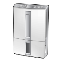
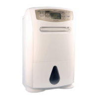
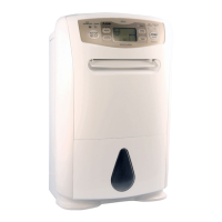
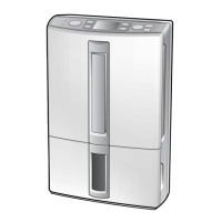
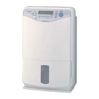
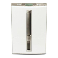
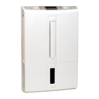
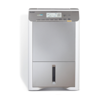
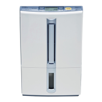
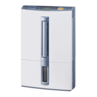
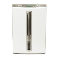
Identifies and describes components located on the front and rear of the unit.
Explains the control panel buttons, modes, and LCD indicators for operation.
Details the wiring diagram and lists safety devices incorporated in the unit.
Presents detailed diagrams of the power and operation control boards.
Lists the functions and operational status of components for each operating mode.
Explains the coolant circuit and provides insights on performance, including FAQs.
Outlines critical safety precautions to follow during failure diagnosis and troubleshooting.
Provides a step-by-step flowchart for diagnosing unit malfunctions and failures.
Details testing procedures and resistance values for key internal components.
Explains how to deactivate the restart lock and the functions activated during the self-test.
Describes modes for testing the unit's LED indicators, LCD panel, fan, operation history, and demo program.
Addresses common unit symptoms with their likely causes and recommended remedies.
Explains error codes displayed on the digital panel and how to resolve them.
Provides instructions for cleaning the unit, water tank, pre-filter, and air filter.
Guides on air filter replacement, unit storage, and disposal procedures.
Lists essential checks after repair and guidance for customer explanation.
Highlights essential safety precautions for disassembling and reassembling the unit.
Step-by-step guides for removing the water tank, front panel, and air filter.
Details on removing the front casing assembly and control boards.
Instructions for removing power control board, condenser, and rear casing.
Guides on removing stepping motor, sensors, solenoid valve, and plug cord.
Instructions for removing the blower fan, motor, and the entire fan assembly.
Details on removing the float switch and the drainpan assembly.
Guides on removing the compressor and heat exchanger assembly.
Exploded view diagram illustrating the casing and structural parts of the unit.
List of casing and structural parts with part numbers and compatibility information.
Continuation of the parts list for casing and structural components.
List of electrical parts including part numbers and compatibility.
List of compressor-related parts with part numbers and compatibility.