EasyManua.ls Logo

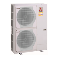
Mitsubishi Electric Mr.SERVICE PUHZ-HRP100YHA2 User Manual

Mitsubishi Electric Mr.SERVICE PUHZ-HRP100YHA2
118 pages
To Next Page IconTo Next Page
Page #1 background imageLoading...
Page #1 background image
SERVICE MANUAL
No.OCH425
REVISED EDITION-B
SPLIT-TYPE, HEAT PUMP AIR CONDITIONERS
R410A
December 2009
PUHZ-HRP71VHA
PUHZ-HRP100VHA
PUHZ-HRP100YHA
PUHZ-HRP125YHA
NOTE:
• This manual describes only
service data of the outdoor
units.
• RoHS compliant products
have <G> mark on the spec
name plate.
PARTS CATALOG (OCB425)
Outdoor unit
[model names]
PUHZ-HRP71VHA
PUHZ-HRP100VHA
PUHZ-HRP100YHA
PUHZ-HRP125YHA
PUHZ-HRP71VHA2
PUHZ-HRP100VHA2
PUHZ-HRP100YHA2
PUHZ-HRP125YHA2
[Service Ref.]
PUHZ-HRP71VHA
PUHZ-HRP100VHA
PUHZ-HRP100YHA
PUHZ-HRP125YHA
PUHZ-HRP71VHA2
PUHZ-HRP71VHA2R1
PUHZ-HRP100VHA2
PUHZ-HRP100VHA2R1
PUHZ-HRP100YHA2
PUHZ-HRP100YHA2R1
PUHZ-HRP125YHA2
PUHZ-HRP125YHA2R1
CONTENTS
1. TECHNICAL CHANGES ·······························2
2. REFERENCE MANUAL ································2
3. SAFETY PRECAUTION ·······························3
4. FEATURES ···················································7
5. SPECIFICATIONS ········································8
6. DATA ·····························································9
7. OUTLINES AND DIMENSIONS··················12
8. WIRING DIAGRAM ·····································14
9. WIRING SPECIFICATIONS ························20
10. REFRIGERANT SYSTEM DIAGRAM ········25
11. TROUBLESHOOTING ································27
12. FUNCTION SETTING ·································85
13.
MONITORING THE OPERATION DATA BY THE REMOTE CONTROLLER
····92
14. EASY MAINTENANCE FUNCTION ·········102
15. DISASSEMBLY PROCEDURE ·················107
Revision:
PUHZ-HRP71/100VHA2R1 and
PUHZ-HRP100/125YHA2R1
are added in REVISED
EDITION-B.
Some descriptions have been
modified.
• Please void OCH425
REVISED EDITION-A.

Questions and Answers:

Mitsubishi Electric Mr.SERVICE PUHZ-HRP100YHA2 Specifications

General IconGeneral
BrandMitsubishi Electric
ModelMr.SERVICE PUHZ-HRP100YHA2
CategoryAir Conditioner
LanguageEnglish

Summary

Technical Changes

Reference Manual

Indoor Unit Service Manual

Lists service manuals for indoor units and their reference numbers.

Safety Precautions

Always Observe for Safety

General safety precautions before and during repair service.

Cautions Related to New Refrigerant

Cautions for units utilizing R410A refrigerant.

Precautions When Reusing Existing R22 Refrigerant Pipes

Cautions for Refrigerant Piping Work

Thickness of Pipes

Specifies minimum pipe thickness for R410A refrigerant.

Dimensions of Flare Cutting and Flare Nut

Details flare cutting and flare nut dimensions for R410A.

Tools for R410A

Lists tools required for R410A and compatibility with R22/R407C.

Features

High Heating Capacity

Describes the unit's high heating capacity, even at low temperatures.

High Speed Heating Start Up

Details improvements in heating startup time and defrosting efficiency.

Wide Heating Range

Specifies the extended heating operational range down to -25°C.

Chargeless System

Explains the pre-charged refrigerant system for simplified installation.

Refrigerant Leakage Detection Function

Describes the unit's ability to detect refrigerant leaks.

Specifications

Data

Refilling Refrigerant Charge (R410A : kg)

Table showing refrigerant charge amounts based on piping length.

Compressor Technical Data

Lists technical data for the compressor winding resistance.

Noise Criterion Curves

Standard Operation Data

Outlines and Dimensions

Free Space (Around the Unit)

Specifies required free space around the unit for installation and service.

Service Space

Details the space required for service access to the unit.

Foundation Bolts

Specifies requirements for securing the unit with foundation bolts.

Piping-Wiring Directions

Indicates the directions from which piping and wiring connections can be made.

Wiring Diagram

Wiring Diagram

Wiring Diagram

Wiring Diagram

Wiring Diagram

Wiring Diagram

Wiring Specifications

Field Electrical Wiring (Power Wiring Specifications)

Specifies wire size, circuit rating, and wiring diagrams for electrical connections.

Separate Indoor Unit/ Outdoor Unit Power Supplies

Indoor – Outdoor Connecting Cable

M-NET Wiring Method

M-NET Wiring Method

M-NET Address Setting

Explains how to set M-NET addresses using rotary switches.

Refrigerant Address Setting

Details how to set refrigerant addresses for multiple grouping systems.

Regulations in Address Settings

Rules for setting M-NET and refrigerant addresses in multiple grouping systems.

Refrigerant System Diagram

Refrigerant Recovering (Pump Down)

Unit Replacement Operation (Except for PUHZ-HRP·HA2R1)

Start and Finish of Test Run

Troubleshooting

Troubleshooting

Summary of error code display and corresponding service actions.

Check Point Under Test Run

Essential checks to perform before initiating a test run.

How to Proceed “Self-Diagnosis”

When a Problem Occurs During Operation

How to handle error displays when a problem occurs during operation.

Self-Diagnosis During Maintenance or Service

How to recall and check error code history during maintenance.

Remote Controller Diagnosis

Malfunction-diagnosis Method by Wireless Remote Controller

Self-Diagnosis Action Table

Troubleshooting by Inferior Phenomena

Phone Calls From Customers

How to Check the Parts

Linear Expansion Valve

Operation Summary of the Linear Expansion Valve

Summary of how the linear expansion valve operates and is controlled.

Linear Expansion Valve Operation

Details valve operation based on pulse signals and potential sounds.

Emergency Operation

When the Error Codes Shown Below Are Displayed...

Lists error codes that allow emergency operation.

Check the Following Items and Cautions for Emergency Operation

Important checks and cautions before initiating emergency operation.

Emergency Operation Procedure

Step-by-step instructions for activating emergency operation.

Releasing Emergency Operation

Instructions for deactivating emergency operation.

Operation Data During Emergency Operation

Test Point Diagram

Outdoor Noise Filter Circuit Board

Outdoor Noise Filter Circuit Board

Outdoor Power Circuit Board

Outdoor Power Circuit Board

Outdoor Power Circuit Board

Outdoor Converter Circuit Board

Active Filter Module

Function of Switches, Connectors and Jumpers

Function of Switches

Explains the function and action of DIP switches and push switches.

Special Function

Display Function of Inspection for Outdoor Unit

Function Setting

Unit Function Setting by the Remote Controller

Guide to setting unit functions using the remote controller.

Meaning of "Function Setting"

Explains the meaning of function settings, specifically for indoor temperature detection.

Selecting Functions Using the Wired Remote Controller

Selecting Functions Using the Wireless Remote Controller (Type C)

Monitoring the Operation Data by the Remote Controller

How to "Monitor the Operation Data"

Step-by-step guide to enter maintenance mode and view operation data.

Request Code List

Easy Maintenance Function

Maintenance Mode Operation Method

Steps to activate and use the maintenance mode for inspection.

Guide for Operation Condition

Initial Settings for Refrigerant Leakage Detection Function

How to Select the "Refrigerant Leakage Detection" Mode

Steps to select the refrigerant leakage detection mode.

How to Start the Initial Learning

How to initiate the initial learning process for leakage detection.

Disassembly Procedure

Removing the Service Panel and Top Panel

Instructions for removing the service panel and top panel.

Removing the Fan Motor (MF1, MF2)

Instructions for removing the fan motor components.

Removing the Electrical Parts Box

Instructions for removing the electrical parts box and its contents.

Related product manuals