EasyManua.ls Logo

Mitsubishi Electric Mr. Slim MUY-D30NA User Manual

Mitsubishi Electric Mr. Slim MUY-D30NA
44 pages
To Next Page IconTo Next Page
Page #1 background imageLoading...
Page #1 background image
SERVICE MANUAL
CONTENTS
1. TECHNICAL CHANGES ··································· 3
2. PART NAMES AND FUNCTIONS ····················· 3
3. SPECIFICATION ················································ 4
4. OUTLINES AND DIMENSIONS ························ 6
5. WIRING DIAGRAM ············································ 7
6. REFRIGERANT SYSTEM DIAGRAM ··············11
7. DATA ································································ 13
8. ACTUATOR CONTROL ··································· 20
9. SERVICE FUNCTIONS ··································· 21
10. TROUBLESHOOTING ····································· 22
11. DISASSEMBLY INSTRUCTIONS ···················· 41
Models
MUZ-D30NA / -
1
/ -
U1
/ -
U2
MUZ-D36NA / -
1
/ -
U1
/ -
U2
MUY-D30NA / -
1
MUY-D36NA / -
1
SPLIT-TYPE AIR CONDITIONERS
OUTDOOR UNIT
Indoor unit service manual
MSZ-D•NA Series (OBH501)
MSY-D•NA Series (OBH501)
NOTE:
RoHS compliant products have <G> mark on the spec name plate.
TM
HFC
utilized
R410A
No. OBH502
REVISED EDITION-B
PARTS CATALOG (OBB502)
Revision B:
• MUZ-D•NA-
1
/-
U2
and MUY-D•NA-
1
have
been corrected.
Please void OBH502 REVISED EDITION-A.
Question and Answer IconNeed help?

Do you have a question about the Mitsubishi Electric Mr. Slim MUY-D30NA and is the answer not in the manual?

Mitsubishi Electric Mr. Slim MUY-D30NA Specifications

General IconGeneral
Phase1
RefrigerantR410A
Cooling Capacity30000 BTU
Seasonal Energy Efficiency Ratio (SEER)16.0
SEER16.0
Power Supply208/230V
Voltage (V)208/230V
Noise Level (Indoor Unit)49 dB

Summary

TECHNICAL CHANGES

New Model Introduction and Changes

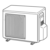
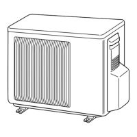
Details new outdoor unit models, wiring diagram, and fan motor modifications.

PART NAMES AND FUNCTIONS

SPECIFICATION

OUTLINES AND DIMENSIONS

WIRING DIAGRAM

REFRIGERANT SYSTEM DIAGRAM

DATA

Cooling Performance Data

Provides detailed cooling capacity performance data under various conditions.

Cooling Capacity Correction Factors

Details correction factors for cooling capacity based on refrigerant piping length.

Heating Performance Data

Provides detailed heating capacity performance data under various conditions.

ACTUATOR CONTROL

Outdoor Fan Motor Control Logic

Explains the ON/OFF control logic for the outdoor fan motor relative to the compressor.

Reversing Valve (R.V.) Coil Control Logic

Describes the control operation for the reversing valve coil in cooling and heating modes.

Sensor and Actuator Relationships

Maps sensors to their purposes and related actuators (Compressor, LEV, etc.).

SERVICE FUNCTIONS

Pre-Heat Control Function

Details how to activate the pre-heat function to prevent compressor issues.

Defrost Finish Temperature Setting

Explains how to change the defrost finish temperature setting.

TROUBLESHOOTING

Troubleshooting Safety Precautions

Lists essential safety precautions and general checks before troubleshooting.

Failure Mode Recall Function

Explains how to recall and interpret failure modes using LED indicators.

Troubleshooting Check Table

A detailed table correlating LED indications with specific failure modes and correspondence.

Component Trouble Criteria

Provides check methods and criteria for diagnosing key components.

Troubleshooting Flowcharts

Step-by-step diagnostic guides for inverter/compressor, thermistors, R.V. coil, etc.

Test Point and Voltage Diagrams

Illustrates electronic board test points and voltage specifications for diagnosis.

DISASSEMBLY INSTRUCTIONS

Cabinet Removal Procedures

Step-by-step guide for removing the outdoor unit's cabinet.

Electronic Assembly Removal

Instructions for removing electronic assemblies like the inverter and PC boards.

R.V. Coil Removal (MUZ)

Specific steps for removing the Reversing Valve (R.V.) coil for MUZ models.

Thermistor Component Removal

Details on how to remove defrost, discharge, heat exchanger, and ambient thermistors.

Outdoor Fan Motor Removal

Steps for safely removing the outdoor fan motor assembly.

Compressor and 4-Way Valve Removal

Instructions for removing the compressor and the 4-way valve, including gas recovery.

Reactor Component Removal

Procedure for disconnecting and removing the reactor component.

Related product manuals