EasyManua.ls Logo

Mitsubishi Electric Mr. Slim MUY-D36NA User Manual

Mitsubishi Electric Mr. Slim MUY-D36NA
44 pages
To Next Page IconTo Next Page
Page #1 background imageLoading...
Page #1 background image
SERVICE MANUAL
CONTENTS
1. TECHNICAL CHANGES ··································· 3
2. PART NAMES AND FUNCTIONS ····················· 3
3. SPECIFICATION ················································ 4
4. OUTLINES AND DIMENSIONS ························ 6
5. WIRING DIAGRAM ············································ 7
6. REFRIGERANT SYSTEM DIAGRAM ··············11
7. DATA ································································ 13
8. ACTUATOR CONTROL ··································· 20
9. SERVICE FUNCTIONS ··································· 21
10. TROUBLESHOOTING ····································· 22
11. DISASSEMBLY INSTRUCTIONS ···················· 41
Models
MUZ-D30NA / -
1
/ -
U1
/ -
U2
MUZ-D36NA / -
1
/ -
U1
/ -
U2
MUY-D30NA / -
1
MUY-D36NA / -
1
SPLIT-TYPE AIR CONDITIONERS
OUTDOOR UNIT
Indoor unit service manual
MSZ-D•NA Series (OBH501)
MSY-D•NA Series (OBH501)
NOTE:
RoHS compliant products have <G> mark on the spec name plate.
TM
HFC
utilized
R410A
No. OBH502
REVISED EDITION-B
PARTS CATALOG (OBB502)
Revision B:
• MUZ-D•NA-
1
/-
U2
and MUY-D•NA-
1
have
been corrected.
Please void OBH502 REVISED EDITION-A.
Question and Answer IconNeed help?

Do you have a question about the Mitsubishi Electric Mr. Slim MUY-D36NA and is the answer not in the manual?

Mitsubishi Electric Mr. Slim MUY-D36NA Specifications

General IconGeneral
BrandMitsubishi Electric
ModelMr. Slim MUY-D36NA
CategoryAir Conditioner
LanguageEnglish

Summary

Technical Changes

Model and Component Updates

Details changes in model designations, wiring, and fan motor.

Part Names and Functions

Outdoor Unit Component Identification

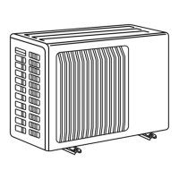
Provides an illustrated guide to the components of the outdoor unit.

Specifications

Refrigerant Piping and Charge

Specifies maximum refrigerant piping length, height difference, and additional charge.

Outlines and Dimensions

Wiring Diagram

Refrigerant System Diagram

Data

Performance Data

Detailed cooling and heating performance data including capacity and corrections.

Performance Curves

Graphical representation of capacity and input vs. operational frequency.

Condensing Pressure

Charts showing condensing and suction pressure based on temperature.

Standard Operation Data

Key operational parameters for cooling and heating modes.

Capacity and Input Correction by Inverter Frequency

Factors for adjusting capacity and input based on compressor frequency.

Actuator Control

Outdoor Fan Motor Control

Explains the ON/OFF timing for the outdoor fan motor relative to the compressor.

R.V. Coil Control

Describes the control logic for the 4-way reversing valve in cooling and heating.

Sensor and Actuator Relationships

Table showing how sensors relate to specific actuators for control.

Service Functions

Pre-Heat Control

Procedure to activate compressor winding heating to prevent moisture issues.

Defrost Setting Adjustment

How to change the defrost finish temperature setting via dip switch.

Troubleshooting

Cautions on Troubleshooting

Important safety and handling precautions before starting troubleshooting.

Failure Mode Recall Function

Steps to recall and interpret fault codes indicated by indoor/outdoor unit LEDs.

Outdoor Unit Failure Mode Table

Lists abnormal points, LED indications, conditions, and correspondences for troubleshooting.

Troubleshooting Check Table

A comprehensive table detailing symptoms, LED indications, and corrective actions.

Troubleshooting Criteria for Main Parts

Methods and criteria for checking the resistance of key components.

Troubleshooting Flowcharts

Step-by-step guides for diagnosing specific component failures (e.g., compressor, thermistors).

Electromagnetic Noise Issues

Guidance on diagnosing and mitigating electromagnetic noise interference.

Disassembly Instructions

Terminal Detaching Points

Explains how to detach terminals with and without locking mechanisms.

Cabinet Removal

Step-by-step instructions for removing the outer cabinet of the unit.

Inverter Assembly and Board Removal

Procedures for removing the inverter assembly, P.C. boards, and power board.

Component Removal

Instructions for removing thermistors and the outdoor fan motor.

Compressor and 4-way Valve Removal

Steps for removing the compressor and the 4-way valve.

Related product manuals