Do you have a question about the Mitsubishi Electric Mr.Slim MUZ09UN and is the answer not in the manual?
| Category | Air Conditioner |
|---|---|
| Brand | Mitsubishi Electric |
| Series | Mr.Slim |
| Refrigerant Type | R410A |
| Model Name | MUZ-09UN |
| Cooling Capacity (BTU/h) | 9000 |
| Cooling Capacity (kW) | 2.6 |
| Power Supply | 230V/1ph/60Hz |
| Outdoor Unit Dimensions (HxWxD, mm) | 550 x 800 x 285 |
Lists the specific indoor and outdoor unit models covered by the manual.
Explains how inverter technology ensures consistent room temperature and comfort.
Describes the benefits of inverter technology for efficient cooling and heating performance.
Highlights the energy efficiency improvements offered by inverter technology.
Notes a reduction in noise levels for the indoor unit.
Details the features of the wireless remote controller, including the "I Feel Control" function.
Explains how to control airflow direction using the remote controller.
Describes the function that automatically restarts the unit after a power outage.
Highlights the advanced design and benefits of the rotary compressor.
Explains how the twin-rotary compressor reduces vibration and noise.
Notes a reduction in noise levels for the outdoor unit.
Identifies and labels parts of the indoor unit for MSZ09UN/MSZ12UN.
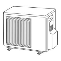
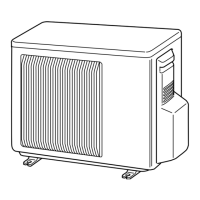
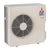
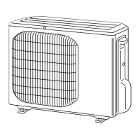
Identifies and labels parts of the outdoor unit for MUZ09UN/MUZ12UN.
Provides a diagram and labels for the wireless remote controller.
Lists indoor unit specs like dimensions, power, airflow, and sound level.
Lists outdoor unit specs like finish, power, and refrigerant details.
Details refrigerant pipe sizes, connection methods, and lengths.
Provides max refrigerant pipe lengths for different models.
Specifies max allowable height difference between indoor and outdoor units.
Presents cooling capacity data for various temperatures and conditions.
Shows correction factors for cooling capacity based on piping length.
Presents heating capacity data for various temperatures and conditions.
Instructions for using emergency operation for fixed compressor frequencies.
Cooling performance curves showing capacity and power consumption vs. outdoor temperature.
Heating performance curves showing capacity and power consumption vs. outdoor temperature.
Heating performance curves for MSZ12UN/MUZ12UN, showing capacity and power consumption.
Condensing and suction pressure charts for MSZ09UN cooling operation.
Condensing and suction pressure charts for MSZ09UN heating operation.
Condensing and suction pressure charts for MSZ12UN heating operation.
Standard data for total capacity, SHF, input, and rated frequency.
Electrical circuit specifications for indoor and outdoor units.
Refrigerant circuit specifications including pressures and temperatures.
Standard operation data for indoor/outdoor unit temperatures, fan speed, and airflow.
Wiring diagrams and control voltage information for power supply.
Details rated and guaranteed voltage ranges for indoor and outdoor units.
Lists operating ranges for cooling/heating based on temperatures and humidity.
Provides data on outlet air speed and coverage range.
Specifies additional refrigerant charge required for different piping lengths.
Lists guaranteed voltage ranges for indoor and outdoor units.
Specifies that air flow should be set to MAX.
Lists the main readings to be monitored during operation.
Provides instructions on how to measure temperature differences for service.
Graphs showing cooling capacity correction factors vs. indoor WB temp and frequency.
Graphs showing total input correction factors vs. indoor WB temp and frequency.
Correction factors for MSZ09UN cooling capacity/input related to compressor frequency.
Correction factors for MSZ12UN cooling capacity/input related to compressor frequency.
Graphs showing heating capacity correction factors vs. indoor DB temp and frequency.
Graphs showing total input correction factors vs. indoor DB temp and frequency.
Correction factors for MSZ09UN heating capacity/input related to compressor frequency.
Correction factors for MSZ12UN heating capacity/input related to compressor frequency.
Dimensional drawings and specifications for the MSZ09UN indoor unit.
Dimensional drawings and specifications for the MSZ12UN indoor unit.
Illustrates required clearance space around the outdoor unit for proper ventilation.
Wiring diagram for the indoor unit of the MSZ09UN model.
Wiring diagram for the indoor unit of the MSZ12UN model.
Illustrates the refrigerant flow and components for the MSZ09UN/MUZ09UN model.
Illustrates the refrigerant flow and components for the MSZ12UN/MUZ12UN model.
Diagram and labels for wireless remote controller buttons and functions.
Explains the operation indicator lamp and its meaning.
Describes how room temperature dictates the operation mode in "I FEEL CONTROL".
Explains how initial room temp influences set temp in "I FEEL CONTROL".
Details the "Fuzzy control" feature that adjusts set temp based on user preference.
Explains indoor fan speed control and coil frost prevention in COOL mode.
Indoor fan speed and compressor/fan logic for MSZ09UN in DRY mode.
Compressor and fan operation logic for MSZ12UN in DRY mode.
Indoor fan speed control in AUTO mode for MSZ09UN/MSZ12UN in HEAT mode.
Controls to prevent cold air blow during heating for MSZ09UN/MSZ12UN.
Describes how warm air control works based on various conditions.
Explains indoor fan operation when the thermostat is OFF.
Details compressor frequency control for high pressure protection in HEAT mode.
Conditions and procedures for defrosting operation.
Describes the control of the R.V. coil during different operation modes.
Details the operation of the unit in COOL mode.
Details the operation of the unit in DRY mode.
Details the operation of the unit in HEAT mode.
Explains the feedback control for indoor fan motor rotational frequency.
Describes the protection mechanism for fan motor lock-up.
Details vane motor drive, angle changes, positioning, and auto mode.
How to select swing mode for vertical vane movement.
How horizontal vane angle changes to prevent cold air blow in HEAT operation.
Step-by-step guide for setting ON/OFF timers and cancellation.
Important note regarding the use of the emergency operation switch.
Visual indicators for emergency operation status on MSZ09UN/MSZ12UN.
Describes the function of the current-limiting resistor during power-on.
Explains the power supply conversion and control at normal operation.
Explains how power factor is improved in the inverter circuit.
Describes the noise filter circuit and its function.
Details the function and components of the IPM.
Overview of how operational frequency is controlled.
How frequency is set based on temperature difference at start-up and after.
Details compressor frequency control for high discharge temperature protection.
Explains the concept and determination of optimal voltage control.
Overview of the LEV control system and its adjustments.
Table and graph showing target discharge temperatures for different frequencies.
Table showing LEV opening pulse values for different frequencies.
How to change defrost finish temperature using a jumper wire.
Method to shorten set time using short circuits for service.
Instructions for modifying P.C. boards for individual indoor unit operation.
Steps to disable the auto restart function.
Important notes regarding auto restart function operation and power failures.
General precautions and checks before troubleshooting.
Steps to follow for diagnosing issues using the operation indicator lamp.
Instructions for replacing remote controller batteries and resetting the unit.
Entry point for diagnosing unit issues based on operational status.
Covers flash codes (1-7 times) indicating specific component failures.
Guides to checking specific components like thermistors, fan motors, and control boards.
Explains the meaning of different flashing patterns of the operation indicator lamp.
A table mapping symptoms, abnormal points, detection methods, and checkpoints.
A table detailing LED indications, symptoms, detection methods, and checkpoints for outdoor unit errors.
Check methods and criteria for room, indoor coil, defrost, discharge, and fin thermistors.
Check methods and criteria for the compressor and indoor fan motor.
Check methods and criteria for outdoor fan motor and vane motor.
Check methods and criteria for the R.V. coil and expansion valve.
Procedure to check for balanced voltage between compressor terminals.
Procedure to check resistance between IPM terminals.
Procedure to check compressor winding resistance for shorts or opens.
Procedure to measure compressor operation time until it stops due to overcurrent.
Troubleshooting steps for the indoor fan motor when it does not operate.
Steps to diagnose issues with the remote controller and receiver P.C. board.
Troubleshooting for the indoor electronic control P.C. board.
Checks for abnormalities in outdoor unit thermistors.
Procedure to check the R.V. coil for defects.
Troubleshooting steps for the outdoor fan motor.
Steps to check the power supply to the outdoor unit.
Checks the rush current limiting circuit and resistor.
Procedure to check the expansion valve (LEV) for proper operation.
Troubleshooting steps for mis-wiring and serial signal errors.
Diagram showing test points and voltages on the MSZ09UN indoor control board.
Diagram showing test points and voltages on the MSZ12UN indoor control board.
Resistance charts for fin, defrost, and discharge temperature thermistors.
Layout diagrams for the noise filter and relay P.C. boards.
Tables detailing relay operations for different modes and conditions.
Specific relay assignments for the indoor fan motor based on speed.
Step-by-step guides for removing indoor unit components.
Steps to remove the electrical box from the indoor unit.
Instructions for removing the vane motor.
Steps for removing the line flow fan and indoor fan motor.
Steps to remove the front panel of the MSZ12UN indoor unit.
Instructions for removing the control, receiver, and display boards.
Steps to remove the electrical box from the MSZ12UN indoor unit.
Instructions for removing the vane motor from the MSZ12UN unit.
Steps for removing the fan motor and line flow fan from the MSZ12UN unit.
Steps for removing the outdoor unit cabinet.
Instructions for removing the inverter assembly.
Steps to remove the noise filter P.C. board.
Instructions for removing the relay P.C. board.
Steps to remove the electronic control P.C. board.
Instructions for removing the propeller and outdoor fan motor.
Detailed steps for removing the compressor, including refrigerant recovery.
List of structural parts for the MSZ09UN indoor unit.
List of accessories and remote controller parts.
Parts list for the indoor unit heat exchanger.
List of accessories and remote controller parts for the MSZ12UN.
Parts list for the indoor unit heat exchanger of the MSZ12UN model.
Servicing note for refrigerant pipes, referencing another section.
Information on optional refrigerant extension pipes and their specifications.
Details on the air cleaning filter, its life, and maintenance.
Information about the deodorizing filter, its cleaning, and replacement.
Lists the part number for the drain socket set.