Do you have a question about the Mitsubishi Electric Mr.Slim MUZ-GC35NA - C1 and is the answer not in the manual?
| Brand | Mitsubishi Electric |
|---|---|
| Model | Mr.Slim MUZ-GC35NA - C1 |
| Category | Air Conditioner |
| Language | English |
Details main electric parts, their specifications, and rating conditions.
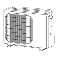
Specifies minimum clearances needed around the outdoor unit for proper operation.
Electrical wiring schematic for MUZ-GC25NA and MUZ-GC35NA models.
Electrical wiring schematic for MUZ-GC50NA and MUZ-GC60NA models.
Electrical wiring schematic for MUZ-GC50NA-C2 model.
Electrical wiring schematic for MUZ-GC60NA-C2 model.
Electrical wiring schematic for MUZ-GC71NA model.
Illustrates the refrigerant flow and components for MUZ-GC25NA/35NA.
Illustrates the refrigerant flow and components for MUZ-GC50NA-C1.
Illustrates the refrigerant flow and components for MUZ-GC50NA-C2.
Illustrates the refrigerant flow and components for MUZ-GC60NA-C1.
Illustrates the refrigerant flow and components for MUZ-GC60NA-C2.
Illustrates the refrigerant flow and components for MUZ-GC71NA.
Provides guidelines for calculating extra refrigerant charge.
Shows cooling capacity and total input across various conditions.
Details how compressor frequency affects capacity and input.
Instructions on how to perform a fixed-frequency test run operation.
Plots low pressure and unit current against ambient conditions.
Presents performance data for heating operation.
Describes the ON/OFF timing and interlocking of the outdoor fan motor.
Explains the control logic for the 4-way reversing valve.
Maps sensors to their corresponding actuators and functions.
Details how to change the defrost finish temperature.
Explains how to activate pre-heat control for low temperatures.
Important safety and preparatory steps before troubleshooting.
Procedure to recall and check memorized failure modes.
Step-by-step flowchart for detailed outdoor unit failure recall.
Lists outdoor unit symptoms, LED indications, and causes.
Symptom-based check table for troubleshooting.
Diagnostic flowcharts for inverter and compressor issues.
Steps to check for open phase faults in the inverter system.
Steps to check compressor operation and winding.
How to measure compressor operation time before overcurrent stop.
Procedure to diagnose and resolve compressor start failures.
Method to test defrost, discharge, ambient, and heat exchanger thermistors.
Steps to check the functionality of the R.V. coil.
Diagnostic steps for the outdoor fan motor.
Verifies the input voltage and internal power supply.
Procedure to test the expansion valve operation and resistance.
Diagnostic steps for the inverter P.C. board.
Identifies and resolves miswiring and serial communication errors.
Procedure to test the high-pressure switch functionality.
Addresses issues of electromagnetic noise affecting TVs or radios.
Identifies test points and voltage readings on the inverter P.C. board.
Pin assignments and test points for the outdoor control board.
Diagram showing the layout of the noise filter P.C. board.
Diagram showing the layout and connections on the outdoor power board.
Step-by-step guide for removing panels and components.
Step-by-step guide for removing panels and components for larger models.