Do you have a question about the Mitsubishi Electric Mr.Slim MUZ-GC60NA - C2 and is the answer not in the manual?
| Refrigerant | R410A |
|---|---|
| Power Source | Electric |
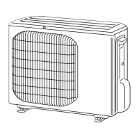
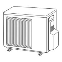
| Outdoor Unit Dimensions (H x W x D) | 840 x 880 x 330 mm |
| Weight (Indoor Unit) | 11 kg |
| Weight (Outdoor Unit) | 55 kg |
Details capacity and input data under various operating conditions for different models.
Correction factors for capacity and input based on compressor operational frequency.
Procedure for conducting fixed-frequency test run operations on the unit.
Charts illustrating outdoor low pressure and unit current relative to ambient conditions.
Performance characteristics and outdoor unit current during heating operation.
Explains the ON/OFF control logic for the outdoor fan motor interlocking with the compressor.
Details the control states for the R.V. coil during cooling, heating, and dry modes.
Mapping of main sensors to actuators (compressor, fan, coils) for operational control.
Procedure to modify the defrost finish temperature using jumper wires.
Method to activate pre-heat control for compressor protection in low temperatures.
Important safety checks and precautions before performing troubleshooting procedures.
Steps to access and interpret stored failure codes for diagnosis.
Table correlating LED indications with specific failure modes and conditions.
Resistance and voltage criteria for troubleshooting key electrical components.
Diagnostic flowcharts for various operational issues and component checks.
Diagrams showing test points on PC boards and associated voltage checks.
Step-by-step guide for removing cabinets and panels for MUZ-GC25/35NA models.
Step-by-step guide for removing cabinets and panels for MUZ-GC50/60/71NA models.