EasyManua.ls Logo

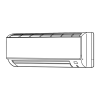
Mitsubishi Electric Mr.Slim MSZ-GC35NA - C2 User Manual

Mitsubishi Electric Mr.Slim MSZ-GC35NA - C2
48 pages
To Next Page IconTo Next Page
Page #1 background imageLoading...
Page #1 background image
SERVICE MANUAL
CONTENTS
1. PART NAMES AND FUNCTIONS ····················· 3
2. SPECIFICATION ················································ 4
3. OUTLINES AND DIMENSIONS ························ 5
4. WIRING DIAGRAM ············································ 7
5. REFRIGERANT SYSTEM DIAGRAM ··············· 9
6. SERVICE FUNCTIONS ··································· 10
7. MICROPROCESSOR CONTROL ··················· 12
8. TROUBLESHOOTING ····································· 18
9. DISASSEMBLY INSTRUCTIONS ···················· 39
Models
MSZ-GC22NA -
C1
MSZ-GC25NA -
C1
MSZ-GC35NA -
C1
MSZ-GC35NA -
C2
MSZ-GC50NA -
C1
MSZ-GC60NA -
C1
MSZ-GC71NA -
C1
SPLIT-TYPE AIR CONDITIONERS
MSZ-GC22/25/35NA
INDOOR UNIT
Outdoor unit service manual
MUZ-GC·NA Series(OBH482)
MXZ-A·NA Series (OB430)
PARTS CATALOG (OBB481)
NOTE:
RoHS compliant products have <G> mark on the spec name plate.
No. OBH481
REVISED EDITION-A
Please void OBH481.
Revision A:
MSZ-GC35NA -
C2
has been added.
Question and Answer IconNeed help?

Do you have a question about the Mitsubishi Electric Mr.Slim MSZ-GC35NA - C2 and is the answer not in the manual?

Mitsubishi Electric Mr.Slim MSZ-GC35NA - C2 Specifications

General IconGeneral
BrandMitsubishi Electric
ModelMr.Slim MSZ-GC35NA - C2
CategoryAir Conditioner
LanguageEnglish

Summary

Part Names and Functions

Specification Details

Outlines and Dimensions

Wiring Diagrams

Refrigerant System Diagram

Service Functions Overview

Microprocessor Control

Wireless Remote Controller Operation

Details the buttons, display, and functions of the wireless remote controller.

Indoor Unit Status Indicators

Explains the meaning of the operation indicator lamps on the indoor unit.

Core Operation Modes

Describes the procedures and features of Cool, Dry, Heat, and Auto modes.

Vane and Airflow Control

Details auto vane operation, horizontal/vertical vane control, and airflow settings.

Timer and Special Operations

Covers timer functions, emergency operation, and auto restart features.

Troubleshooting

Troubleshooting Precautions and Flowcharts

Safety, preliminary checks, and overall diagnostic flowcharts.

Failure Mode Recall and Component Testing

Recalls stored error codes and tests motors, P.C. boards, and sensors.

Subsystem, Wiring, and Interference Checks

Diagnoses control systems, wiring, installation issues, and electromagnetic interference.

Electrical Test Points and Voltages

Provides diagrams and voltage references for P.C. board troubleshooting.

Disassembly Instructions

Disassembly for GC22/25/35 Models

Step-by-step instructions for disassembling panels, boards, motors, and fans.

Disassembly for GC50 Model

Step-by-step instructions for disassembling panels, boards, motors, and fans.

Disassembly for GC60/71 Models

Step-by-step instructions for disassembling panels, boards, motors, and fans.

Related product manuals