Do you have a question about the Mitsubishi Electric Mr.Slim MUZ-GC35NA - C2 and is the answer not in the manual?
| Refrigerant | R410A |
|---|---|
| Indoor Unit Weight | 9 kg |
| Cooling Capacity | 12000 BTU/h |
| Coefficient of Performance (COP) | 3.5 |
| Power Supply | 50 Hz |
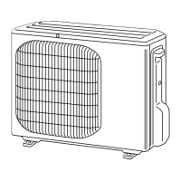
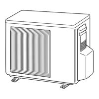
| Outdoor Unit Dimensions (H x W x D) | 550 x 780 x 285 mm |
Details on calculating extra refrigerant charge based on piping length.
Graphs showing cooling capacity and total input under various conditions.
Correction factors for capacity and input based on compressor frequency.
Procedure for testing the unit's operation at fixed frequencies.
Charts showing outdoor low pressure and unit current under cooling operation.
Performance data related to heating operation conditions.
How the outdoor fan motor operates in relation to the compressor.
Operation of the reversing valve (4-way valve) for cooling and heating.
Mapping of sensors to actuators for different models.
How to adjust the defrost finish temperature using jumper wires.
Procedure to activate pre-heat control for low-temperature operation.
Important safety and preparatory steps before troubleshooting.
How to retrieve stored error codes from the unit's memory.
Table listing outdoor unit failure modes, LED indications, and causes.
Table correlating symptoms, LED indications, and troubleshooting steps.
Methods and criteria for checking key components like thermistors and motors.
Step-by-step diagnostic guides for components: compressor, power supply, motors, thermistors, HPS, LEV, P.C. boards, and wiring.
Diagram showing test points and voltage measurements on the inverter board.
Diagram showing test points and component locations on the control board.
Diagram showing components and connections on the noise filter board.
Diagram showing components and connections on the outdoor power board.
Step-by-step guide for removing panels and components for these models.
Step-by-step guide for removing panels and components for these models.
Detailed procedure for removing the inverter and power boards.
Procedure for removing various thermistors from the unit.
Steps for safely removing the compressor and 4-way valve.