EasyManua.ls Logo

Mitsubishi Electric Mr. Slim MUZ-D30NA User Manual

Mitsubishi Electric Mr. Slim MUZ-D30NA
44 pages
To Next Page IconTo Next Page
Page #1 background imageLoading...
Page #1 background image
SERVICE MANUAL
CONTENTS
1. TECHNICAL CHANGES ··································· 3
2. PART NAMES AND FUNCTIONS ····················· 3
3. SPECIFICATION ················································ 4
4. OUTLINES AND DIMENSIONS ························ 6
5. WIRING DIAGRAM ············································ 7
6. REFRIGERANT SYSTEM DIAGRAM ··············11
7. DATA ································································ 13
8. ACTUATOR CONTROL ··································· 20
9. SERVICE FUNCTIONS ··································· 21
10. TROUBLESHOOTING ····································· 22
11. DISASSEMBLY INSTRUCTIONS ···················· 41
Models
MUZ-D30NA / -
1
/ -
U1
/ -
U2
MUZ-D36NA / -
1
/ -
U1
/ -
U2
MUY-D30NA / -
1
MUY-D36NA / -
1
SPLIT-TYPE AIR CONDITIONERS
OUTDOOR UNIT
Indoor unit service manual
MSZ-D•NA Series (OBH501)
MSY-D•NA Series (OBH501)
NOTE:
RoHS compliant products have <G> mark on the spec name plate.
TM
HFC
utilized
R410A
No. OBH502
REVISED EDITION-B
PARTS CATALOG (OBB502)
Revision B:
• MUZ-D•NA-
1
/-
U2
and MUY-D•NA-
1
have
been corrected.
Please void OBH502 REVISED EDITION-A.
Question and Answer IconNeed help?

Do you have a question about the Mitsubishi Electric Mr. Slim MUZ-D30NA and is the answer not in the manual?

Mitsubishi Electric Mr. Slim MUZ-D30NA Specifications

General IconGeneral
BrandMitsubishi Electric
ModelMr. Slim MUZ-D30NA
CategoryAir Conditioner
LanguageEnglish

Summary

1 TECHNICAL CHANGES

New Model Identification

Details new outdoor unit models and their relation to previous versions.

Wiring and Fan Motor Updates

Notes changes made to the wiring diagram and fan motor.

2 PART NAMES AND FUNCTIONS

Model Identification

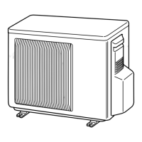
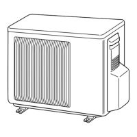
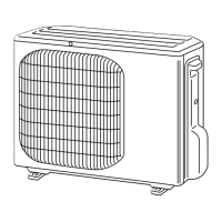
Lists the applicable outdoor unit models for this service manual.

Component Diagram

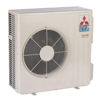
Illustrates outdoor unit parts and air inlet/outlet.

3 SPECIFICATION

Capacity and Power Ratings

Details cooling/heating capacity, power consumption, and EER/COP.

Electrical and Physical Specifications

Covers power supply, dimensions, weight, and connections.

Refrigerant and Piping Details

Lists refrigerant type, oil, and pipe size specifications.

4 OUTLINES AND DIMENSIONS

Dimensional Drawings

Provides overall dimensions and key measurements for the outdoor units.

Required Installation Space

Specifies the necessary clearance around the outdoor unit for operation.

5 WIRING DIAGRAM

Electrical Schematic

Illustrates the electrical connections and layout of the outdoor unit.

Component Identification

Lists and defines various electrical components used in the circuit.

6 REFRIGERANT SYSTEM DIAGRAM

MUZ Series Refrigerant Flow

Illustrates the refrigerant circuit and flow for MUZ models.

MUY Series Refrigerant Flow

Illustrates the refrigerant circuit and flow for MUY models.

MAX. REFRIGERANT PIPING LENGTH and MAX. HEIGHT DIFFERENCE

Maximum Piping Length and Height Difference

Specifies the limits for refrigerant pipe installation length and height.

Additional Refrigerant Charge Calculation

Provides guidelines for adding refrigerant based on pipe length.

7 DATA

7-1 PERFORMANCE DATA

Presents cooling and heating capacity and power consumption data.

Cooling Capacity Corrections

Factors for adjusting cooling capacity based on piping length.

Heating Performance Data

Presents heating capacity and power consumption data.

7-2 PERFORMANCE CURVE

Cooling Performance Curves

Graphs showing capacity and input vs. temperature for cooling.

Heating Performance Curves

Graphs showing capacity and input vs. temperature for heating.

7-3 CONDENSING PRESSURE

MUZ Series Condensing Pressure

Pressure charts for MUZ models under cooling conditions.

MUZ-D36NA Condensing Pressure

Pressure charts for MUZ-D36NA under cooling conditions.

MUY-D30NA Condensing Pressure

Pressure charts for MUY-D30NA under cooling conditions.

MUY-D36NA Condensing Pressure

MUY-D36NA Cooling Pressure Charts

Pressure charts for MUY-D36NA under cooling conditions.

MUZ Series Heating Pressure

Pressure charts for MUZ models under heating conditions.

MUZ-D36NA Heating Pressure

Pressure charts for MUZ-D36NA under heating conditions.

7-4 STANDARD OPERATION DATA

Electrical Specifications Summary

Key electrical parameters for different models and modes.

Refrigerant and Indoor Unit Data

Details refrigerant charge, temperatures, and airflows.

7-5 CAPACITY AND INPUT CORRECTION BY INVERTER OUTPUT FREQUENCY

Cooling Capacity/Input Correction Curves

Graphs showing correction factors for cooling operation.

Heating Capacity/Input Correction Curves

Graphs showing correction factors for heating operation.

7-6 TEST RUN OPERATION

Fixed-Frequency Operation Procedure

Steps for conducting a test run with fixed frequency.

8 ACTUATOR CONTROL

Outdoor Fan Motor Operation

Describes control logic for the outdoor fan motor.

Reversing Valve Coil Control

Explains control sequences for the R.V. coil in heating/cooling.

Sensor and Actuator Relationships

Maps sensors to their corresponding actuators for system control.

9 SERVICE FUNCTIONS

Pre-Heat Control Activation

How to enable compressor winding heating for improved start-up.

Defrost Finish Temperature Adjustment

Method to change the defrost termination temperature setting.

10 TROUBLESHOOTING

General Troubleshooting Precautions

Essential safety and handling guidelines before performing service.

Troubleshooting Procedure Overview

Initial steps to identify and diagnose operational issues.

10-2 FAILURE MODE RECALL FUNCTION

Failure Recall Function Overview

Explains how the unit memorizes and recalls abnormal conditions.

Indoor/Outdoor Unit Failure Recall Flowchart

Step-by-step guide for recalling failure modes.

Releasing Failure Recall Function

Procedures to exit failure recall mode and delete stored data.

2. Flow chart of the detailed outdoor unit failure mode recall function

Outdoor Unit Failure Recall Flowchart

Detailed steps for recalling specific outdoor unit failure modes.

3. Outdoor unit failure mode table

Failure Mode Table (LED Indications)

Lists faults, LED codes, conditions, and corresponding remedies.

10-3 TROUBLESHOOTING CHECK TABLE

Troubleshooting Symptom Codes

Details symptoms, LED indications, conditions, and fixes.

10-4 TROUBLE CRITERION OF MAIN PARTS

Thermistor Resistance Checks

Criteria and methods for checking thermistor resistance.

Compressor and Fan Motor Checks

Normal resistance values for compressor and fan motor.

Coil and Valve Resistance Checks

Resistance criteria for R.V. coil and linear expansion valve.

10-5 TROUBLESHOOTING FLOW

Inverter/Compressor Check Procedure

Steps to diagnose inverter and compressor issues.

B Check of outdoor thermistors

Outdoor Thermistor Checks

Procedure for checking outdoor thermistor resistance.

C Check of R.V. coil

R.V. Coil Check (Heating/Cooling)

Diagnostic steps for R.V. coil operation issues.

D Check of outdoor fan motor

Outdoor Fan Motor Check

Procedure to test the outdoor fan motor.

E Check of power supply

Power Supply Circuit Check

Steps to verify power supply and circuit board voltages.

F Check of compressor start failure

Compressor Start Failure Diagnosis

Steps to identify and resolve compressor start failures.

G Check of LEV

LEV Coil Check

Procedure to check the LEV coil for proper function.

H How to check miswiring and serial signal error

Miswiring and Serial Signal Error Check

Guide to detect and correct wiring issues and signal errors.

I Check of HPS

HPS (High Pressure Switch) Check

Procedure to test the high-pressure switch functionality.

J Check of bus-bar voltage

Bus-Bar Voltage Check

Verifying bus-bar voltage and related LED indications.

K Electromagnetic noise enters into TV sets or radios

Troubleshooting Electromagnetic Noise

Steps to identify and mitigate noise interference with electronics.

10-6 TEST POINT DIAGRAM AND VOLTAGE

Outdoor Electronic Control P.C. Board Layout

Diagram showing test points and voltage measurements.

2. Noise filter P.C. board

Noise Filter P.C. Board Diagram

Layout of the noise filter board with component connections.

3. Outdoor power board

Outdoor Power Board Diagram

Diagram of the power board showing connections and test points.

11 DISASSEMBLY INSTRUCTIONS

Terminal Detaching Points

How to detach terminals with and without locking mechanisms.

Cabinet Removal Procedure

Step-by-step guide to remove the outdoor unit cabinet.

2. Removing the inverter assembly, P.C. board and power board

Inverter Assembly and Board Removal

Steps to remove inverter, electronic, and power boards.

3. Removing R.V. coil (MUZ)

R.V. Coil Removal (MUZ)

Procedure for removing the reversing valve coil on MUZ models.

4. Removing the defrost thermistor (MUZ), discharge temperature thermistor, outdoor heat exchanger temperature thermistor and ambient temperature thermistor

Thermistor Removal

Steps to remove various thermistors from the unit.

5. Removing outdoor fan motor

Outdoor Fan Motor Removal

Procedure for removing the outdoor fan motor.

6. Removing the compressor and 4-way valve

Compressor and 4-Way Valve Removal

Steps to remove the compressor and 4-way valve.

7. Removing the reactor

Reactor Removal

Procedure for removing the reactor component.

Related product manuals