EasyManua.ls Logo

Mitsubishi Electric Mr.Slim MUZ-FE09NA User Manual

Mitsubishi Electric Mr.Slim MUZ-FE09NA
44 pages
To Next Page IconTo Next Page
Page #1 background imageLoading...
Page #1 background image
SERVICE MANUAL
CONTENTS
1. TECHNICAL CHANGES ··································· 2
2. PART NAMES AND FUNCTIONS ····················· 2
3. SPECIFICATION ················································ 3
4. OUTLINES AND DIMENSIONS ························ 5
5. WIRING DIAGRAM ············································ 6
6. REFRIGERANT SYSTEM DIAGRAM ··············· 7
7. DATA ·································································· 9
8. ACTUATOR CONTROL ··································· 16
9. SERVICE FUNCTIONS ··································· 17
10. TROUBLESHOOTING ····································· 17
11. DISASSEMBLY INSTRUCTIONS ···················· 36
Models
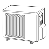
MUZ-FE09NA
MUZ-FE12NA
MUZ-FE18NA
SPLIT-TYPE AIR CONDITIONERS
OUTDOOR UNIT
Indoor unit service manual
MSZ-FE•NA Series (OBH542)
NOTE:
RoHS compliant products have <G> mark on the spec name plate.
TM
HFC
utilized
R410A
No. OBH543
REVISED EDITION-A
PARTS CATALOG (OBB543)
Revision A:
MUZ-FE18NA has been added.
Please void OBH543.
MUZ-FE09NA
MUZ-FE12NA
Question and Answer IconNeed help?

Do you have a question about the Mitsubishi Electric Mr.Slim MUZ-FE09NA and is the answer not in the manual?

Mitsubishi Electric Mr.Slim MUZ-FE09NA Specifications

General IconGeneral
BrandMitsubishi Electric
ModelMr.Slim MUZ-FE09NA
CategoryAir Conditioner
LanguageEnglish

Summary

TECHNICAL CHANGES

REFRIGERANT SYSTEM DIAGRAM

DATA

7-4. STANDARD OPERATION DATA

Comprehensive table of operational data for cooling and heating modes.

7-5. CAPACITY AND INPUT CORRECTION BY INVERTER OUTPUT FREQUENCY

Graphs showing how capacity and input change with inverter frequency.

ACTUATOR CONTROL

SERVICE FUNCTIONS

TROUBLESHOOTING

10-1. CAUTIONS ON TROUBLESHOOTING

Important safety and preliminary checks before troubleshooting.

3. Outdoor unit failure mode table

Table correlating LED indications to specific failure modes and remedies.

10-3. TROUBLESHOOTING CHECK TABLE

Table detailing symptoms, LED indications, conditions, and remedies for faults.

10-4. TROUBLE CRITERION OF MAIN PARTS

Lists criteria for checking the functionality of major components.

10-5. TROUBLESHOOTING FLOW

Provides diagnostic flowcharts for various troubleshooting scenarios.

DISASSEMBLY INSTRUCTIONS

Related product manuals