EasyManua.ls Logo

Mitsubishi Electric Mr.Slim MU-A18ND-S1 User Manual

Mitsubishi Electric Mr.Slim MU-A18ND-S1
36 pages
To Next Page IconTo Next Page
Page #1 background imageLoading...
Page #1 background image
CONTENTS
1. TECHNICAL CHANGES ····································2
2. PART NAMES AND FUNCTIONS······················3
3. SPECIFICATION·················································3
4. OUTLINES AND DIMENSIONS ·························4
5. WIRING DIAGRAM ············································6
6. REFRIGERANT SYSTEM DIAGRAM ················8
7. PERFORMANCE CURVES······························10
8. TROUBLESHOOTING······································12
9. DISASSEMBLY INSTRUCTIONS ····················21
10. PARTS LIST······················································27
11. RoHS PARTS LIST···········································30
SPLIT-TYPE AIR CONDITIONERS
TM
MU-A18ND
MU-A18ND-
MU-A18ND-
MU-A24ND-
MU-A24ND-
MU-A30ND-
MU-A30ND-
S2
S1
S2
S1
S2
S1
Indoor unit service manual
MS-AND Series (OB404)
No. OB405
REVISED EDITION-E
SERVICE MANUAL
Models
OUTDOOR UNIT
NOTE:
• This service manual describes technical data of the outdoor units.
• RoHS compliant products have <G> mark on the spec name plate.
For servicing of RoHS compliant products, refer to the RoHS Parts List.
Please void OB405 REVISED EDITION-D.
Revision E:
SPECIFICATION has been modified.
OB405E.qxp 09.10.14 9:16 AM Page 1
Question and Answer IconNeed help?

Do you have a question about the Mitsubishi Electric Mr.Slim MU-A18ND-S1 and is the answer not in the manual?

Mitsubishi Electric Mr.Slim MU-A18ND-S1 Specifications

General IconGeneral
BrandMitsubishi Electric
ModelMr.Slim MU-A18ND-S1
CategoryAir Conditioner
LanguageEnglish

Summary

Technical Changes

Part Names and Functions

Outdoor Unit Part Identification

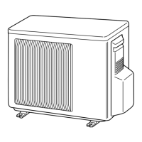
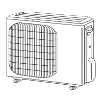
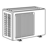
Identifies key external and internal components of the outdoor unit.

Specification

Electrical and Performance Data

Details electrical data, capacity, airflow, and performance metrics for models.

Outlines and Dimensions

MU-A18ND Dimensions and Required Space

Provides dimensional drawings and installation space requirements for the MU-A18ND outdoor unit.

MU-A24ND/MU-A30ND Dimensions and Required Space

Provides dimensional drawings and installation space requirements for MU-A24ND and MU-A30ND units.

Wiring Diagram

MU-A18ND Outdoor Unit Wiring

Electrical wiring diagram for the MU-A18ND outdoor unit.

MU-A24ND Outdoor Unit Wiring

Electrical wiring diagram for the MU-A24ND outdoor unit.

MU-A24ND-S2 and MU-A30ND Outdoor Unit Wiring

Electrical wiring diagrams for MU-A24ND-S2 and MU-A30ND outdoor units.

Refrigerant System Diagram

MU-A18ND Refrigerant Flow

Illustrates the refrigerant circuit for the MU-A18ND outdoor unit.

MU-A24ND Refrigerant Flow

Illustrates the refrigerant circuit for the MU-A24ND outdoor unit.

MU-A30ND Refrigerant Flow and Piping Specs

Shows refrigerant circuit for MU-A30ND and details piping length/height difference.

Performance Curves

Cooling Capacity and Input Correction Factors

Charts showing cooling capacity and input adjustments based on temperatures.

Troubleshooting

Troubleshooting Cautions

Important safety and procedural notes before starting troubleshooting.

Troubleshooting Procedure Flowcharts

Step-by-step guides for diagnosing common operational issues.

Trouble Criterion of Main Parts

Resistance and operational criteria for checking key components.

Compressor/Fan Motor Not Operating (MU-A30ND)

Troubleshooting flow for compressor or fan motor failure in MU-A30ND.

Compressor/Fan Motor Not Stopping (MU-A24ND/MU-A30ND)

Troubleshooting flow for compressor/fan motor failure to stop in MU-A24ND and MU-A30ND.

How to Check Mis-wiring (MU-A30ND)

Procedure to identify and correct mis-wiring issues in MU-A30ND.

Check of LEV (Expansion Valve) (MU-A30ND)

Steps to diagnose and test the Expansion Valve on MU-A30ND.

Check of Outdoor Thermistor (MU-A30ND)

Procedure to check thermistors in the MU-A30ND outdoor unit.

Check of Solenoid Valve Coil (MU-A30ND)

Troubleshooting steps for the solenoid valve coil in MU-A30ND.

Test Point Diagram and Voltage (MU-A30ND)

Diagram showing test points and voltage checks on the MU-A30ND deicer P.C. board.

Disassembly Instructions

Terminal Detaching Points

Instructions on how to detach terminals with locking mechanisms.

MU-A18ND Outdoor Unit Disassembly

Step-by-step guide for disassembling the MU-A18ND outdoor unit.

MU-A24ND Outdoor Unit Disassembly

Step-by-step guide for disassembling the MU-A24ND outdoor unit.

MU-A30ND Outdoor Unit Disassembly

Step-by-step guide for disassembling the MU-A30ND outdoor unit.

Parts List (non-RoHS compliant)

MU-A18ND Outdoor Unit Parts

Lists structural, electrical, and functional parts for MU-A18ND outdoor units.

MU-A24ND/MU-A30ND Outdoor Unit Parts

Lists structural, electrical, and functional parts for MU-A24ND and MU-A30ND units.

RoHS Parts List (RoHS compliant)

MU-A18ND Outdoor Unit RoHS Parts

Lists RoHS compliant structural, electrical, and functional parts for MU-A18ND.

MU-A24ND/MU-A30ND Outdoor Unit RoHS Parts

Lists RoHS compliant structural, electrical, and functional parts for MU-A24ND and MU-A30ND.

Related product manuals