SERVICE MANUAL
CONTENTS
1. REFERENCE MANUAL
...................................
2
2. SAFETY PRECAUTION
...................................
3
3. PARTS NAMES AND FUNCTIONS
.................
4
4. SPECIFICATIONS
............................................
9
5. NOISE CRITERION CURVES
.........................
12
6. OUTLINES AND DIMENSIONS
......................
14
7. WIRING DIAGRAM
.........................................
15
8. REFRIGERANT SYSTEM DIAGRAM
............
16
9. TROUBLESHOOTING
....................................
17
10. SPECIAL FUNCTION
.....................................
32
11. DISASSEMBLY PROCEDURE
.......................
38
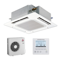
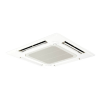
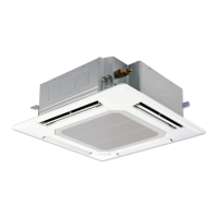
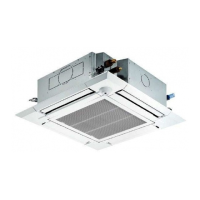
Indoor unit
[Model Name] [Service Ref.]
INDOOR UNIT
PARTS CATALOG (OCB625)
No. OCH625
September 2016
PLA-ZP35EA
PLA-ZP50EA
PLA-ZP60EA
PLA-ZP71EA
PLA-ZP100EA
PLA-ZP125EA
PLA-ZP140EA
PLA-ZP35EA.UK
PLA-ZP50EA.UK
PLA-ZP60EA.UK
PLA-ZP71EA.UK
PLA-ZP100EA.UK
PLA-ZP125EA.UK
PLA-ZP140EA.UK
Notes:
• This manual describes ser-
vice data of the indoor units
only.
• RoHS compliant products
have <G> mark on the spec
name plate.
SPLIT-TYPE, HEAT PUMP AIR CONDITIONERS
SPLIT-TYPE, AIR CONDITIONERS
Model name
indication
Model name
indication for GRILLE
WIRED REMOTE
CONTROLLER
(Option)
WIRELESS REMOTE
CONTROLLER
(Option)