EasyManua.ls Logo

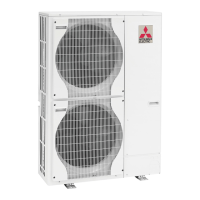
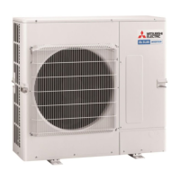
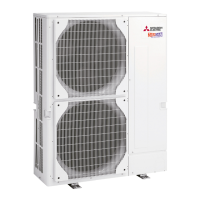
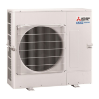
Mitsubishi Electric Mr.Slim PUHZ-P100VKA User Manual

Mitsubishi Electric Mr.Slim PUHZ-P100VKA
110 pages
To Next Page IconTo Next Page
Page #1 background imageLoading...
Page #1 background image
SERVICE MANUAL
No.OCH670
SPLIT-TYPE AIR CONDITIONERS
R410A
September 2017
Outdoor unit
[Model Name]
PUHZ-P100VKA
PUHZ-P125VKA
PUHZ-P140VKA
PUHZ-P100YKA
PUHZ-P125YKA
PUHZ-P140YKA
[Service Ref.]
PUHZ-P100VKA.TH
PUHZ-P100VKA.TH-ET
PUHZ-P100VKA.TH-ER
PUHZ-P125VKA.TH
PUHZ-P125VKA.TH-ET
PUHZ-P125VKA.TH-ER
PUHZ-P140VKA.TH
PUHZ-P140VKA.TH-ET
PUHZ-P140VKA.TH-ER
PUHZ-P100YKA.TH
PUHZ-P100YKA.TH-ET
PUHZ-P100YKA.TH-ER
PUHZ-P125YKA.TH
PUHZ-P125YKA.TH-ET
PUHZ-P125YKA.TH-ER
PUHZ-P140YKA.TH
PUHZ-P125YKA.TH-ET
PUHZ-P125YKA.TH-ER
PARTS CATALOG (OCB670)
CONTENTS
1. REFERENCE MANUAL ································· 2
2. SAFETY PRECAUTION ································· 2
3. SPECIFICATIONS ·········································· 6
4. DATA ······························································· 7
5. OUTLINES AND DIMENSIONS ··················· 10
6. WIRING DIAGRAM ······································ 11
7. WIRING SPECIFICATIONS ·························· 14
8.
REFRIGERANT SYSTEM DIAGRAM
············· 19
9. TROUBLESHOOTING ································· 21
10. FUNCTION SETTING ··································· 78
11.
MONITORING THE OPERATION DATA BY THE REMOTE CONTROLLER
····90
12. EASY MAINTENANCE FUNCTION ··········· 100
13. DISASSEMBLY PROCEDURE ··················· 104

Table of Contents

Question and Answer IconNeed help?

Do you have a question about the Mitsubishi Electric Mr.Slim PUHZ-P100VKA and is the answer not in the manual?

Mitsubishi Electric Mr.Slim PUHZ-P100VKA Specifications

General IconGeneral
BrandMitsubishi Electric
ModelMr.Slim PUHZ-P100VKA
CategoryAir Conditioner
LanguageEnglish

Summary

REFERENCE MANUAL

Indoor Unit Service Manual

Details specific to the indoor unit service manual for various models.

SAFETY PRECAUTION

Always Observe for Safety

Essential safety rules to follow before and during repair service.

Cautions Related to New Refrigerant R410A

Specific safety measures when working with R410A refrigerant.

Precautions When Reusing Existing R22 Refrigerant Pipes

Guidelines for safely reusing R22 refrigerant pipes with new systems.

SPECIFICATIONS

DATA

Refilling Refrigerant Charge (R410A : kg)

Table detailing refrigerant charge amounts based on piping length.

Compressor Technical Data

Technical specifications for compressor winding resistance.

Noise Criterion Curves

Graphs showing sound pressure levels for different frequencies.

Standard Operation Data

Operational data including capacity, current, and temperatures for various models.

OUTLINES AND DIMENSIONS

WIRING DIAGRAM

WIRING SPECIFICATIONS

Field Electrical Wiring (Power Wiring Specifications)

Details on power supply and circuit ratings for electrical connections.

Separate Indoor Unit/ Outdoor Unit Power Supplies

Connection patterns for separate power supplies for indoor and outdoor units.

Indoor – Outdoor Connecting Cable

Specifications for the connecting cable between indoor and outdoor units.

M-NET Wiring Method

Guidelines for wiring M-NET communication lines to avoid noise.

REFRIGERANT SYSTEM DIAGRAM

TROUBLESHOOTING

Troubleshooting Overview and Check Codes

Summary of check codes and general troubleshooting approach.

Test Run Procedures

Steps for performing test runs using wired and wireless remote controllers.

Self-Diagnosis Procedures

Methods for performing self-diagnosis and checking errors.

Self-Diagnosis Action Table

Table detailing actions for specific abnormalities detected.

Troubleshooting of Problems

Common operational problems and their countermeasures.

FUNCTION SETTING

Unit Function Setting by Remote Controller

How to set unit functions like power failure recovery and temperature detection.

Selecting Functions via Wired Remote Controller

Detailed steps for setting functions via wired remote controllers.

Function Selection of Remote Controller

Overview of function selection via remote controller buttons and displays.

Main Menu List of PAR-31MAA

Detailed explanation of settings available in the PAR-31MAA main menu.

MONITORING THE OPERATION DATA BY THE REMOTE CONTROLLER

How to 'Monitor the Operation Data'

Steps to monitor operational data like temperatures and compressor status.

Request Code List

List of request codes and their corresponding data descriptions.

EASY MAINTENANCE FUNCTION

Smooth Maintenance

Procedure for checking maintenance data like temperatures and compressor status.

Guide for Operation Condition

Guide for assessing operation status based on temperature differences.

DISASSEMBLY PROCEDURE

Removing Panels and Fan Motor

Steps to remove the service panel, top panel, and fan motor.

Removing Electrical Parts Box

Steps to remove the electrical components box.

Removing Thermistors and Valves

Steps to remove thermistors, LEV coil, and 4-way valve.

Removing High Pressure Switch and Compressor

Steps to remove high pressure switch and compressor.
Related product manuals