SERVICE TECHNICAL GUIDE
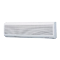
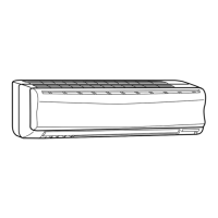
Wireless type
Models
MS-A08ND -
(WH)
· MU-A08ND -
MS-A10ND -
(WH)
· MU-A10ND -
MS-A12ND -
(WH)
· MU-A12ND -
MS-A15ND -
(WH)
· MU-A15ND -
C1C1
C1C1
C1C1
C1C1
No. OBT10
SPLIT-TYPE, AIR CONDITIONERS
CONTENTS
MICROPROCESSOR CONTROL
1.“I FEEL CONTROL” OPERATION·································2
2. COOL OPERATION ·······················································5
3. DRY OPERATION ··························································5
4. FAN OPERATION ··························································5
5. FAN MOTOR CONTROL ···············································5
6. AUTO VANE OPERATION·············································5
7. TIMER OPERATION ······················································7
8. EMERGENCY / TEST OPERATION······························7
TM
OBT10.qxp 05.5.11 11:26 AM Page 1