EasyManua.ls Logo

Mitsubishi Electric MS-A10VD-P1 User Manual

Mitsubishi Electric MS-A10VD-P1
24 pages
To Next Page IconTo Next Page
Page #1 background imageLoading...
Page #1 background image
SERVICE MANUAL
CONTENTS
1. TECHNICAL CHANGES ····································2
2. PART NAMES AND FUNCTIONS······················3
3. SPECIFICATION·················································4
4. OUTLINES AND DIMENSIONS ·························5
5. WIRING DIAGRAM ············································6
6. REFRIGERANT SYSTEM DIAGRAM················6
7. SERVICE FUNCTIONS ······································7
8. TROUBLESHOOTING········································9
9. DISASSEMBLY INSTRUCTIONS ····················18
10. PARTS LIST······················································20
Wireless type
Models
SPLIT-TYPE, AIR CONDITIONERS
MS-A08VD-
MS-A10VD-
MS-A13VD-
P1
P1
P1
TM
No. OB396
Indication of model name
MS-A08VD -
MS-A10VD -
MS-A13VD -
P1
P1
P1
NOTE:
• This service manual describes technical data of indoor units.
As for outdoor units MU-A08VD - ,MU-A10VD - and MU-A13VD - , refer to the service manual OB397.
P1P1P1
OB396--1.qxp 05.3.18 8:59 AM Page 1
Question and Answer IconNeed help?

Do you have a question about the Mitsubishi Electric MS-A10VD-P1 and is the answer not in the manual?

Mitsubishi Electric MS-A10VD-P1 Specifications

General IconGeneral
BrandMitsubishi Electric
ModelMS-A10VD-P1
CategoryAir Conditioner
LanguageEnglish

Summary

Technical Changes

Part Names and Functions

Specification

Outlines and Dimensions

Wiring Diagram

Refrigerant System Diagram

Service Functions

Troubleshooting

Cautions on Troubleshooting

Provides essential safety precautions and checks before beginning any troubleshooting procedures on the air conditioning unit.

Instruction of Troubleshooting

Details the step-by-step process for diagnosing issues, including flowcharts for various operational problems and indicator lamp behaviors.

Troubleshooting Check Table

A table correlating abnormal indicator lamp patterns with symptoms, detection methods, and specific check points for diagnosing faults.

Trouble Criterion of Main Parts

Lists key components and their expected resistance or voltage values for normal and abnormal operation, aiding in fault identification.

Troubleshooting Flow

Presents logical flowcharts for diagnosing specific issues, such as the indoor fan motor not operating or the unit not responding to the remote controller.

Test Point Diagram and Voltage

Illustrates test points on the electronic control P.C. board and power monitor board with associated voltage readings for diagnostic purposes.

Disassembly Instructions

Indoor Unit Operating Procedure

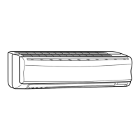
Step-by-step guide for removing the front panel and electronic control P.C. board of the indoor unit, including visual aids.

Parts List

Indoor Unit Structural Parts

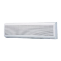
Lists structural components of the indoor unit, including part numbers, quantities, and applicability to different models.

Accessory and Remote Controller

Details the accessories supplied with the unit, such as the remote controller and its holder, with part numbers.

Indoor Unit Electrical Parts and Functional Parts

Provides a comprehensive list of electrical and functional components within the indoor unit, including their part numbers and specifications.

Indoor Unit Heat Exchanger

Lists parts related to the indoor unit's heat exchanger, including unions, with their respective part numbers and sizes.

Air Cleaning Filter

Information on the air cleaning filter, its function, maintenance, and the specific part number required for replacement.

Related product manuals